Gate valves are critical components in industrial piping systems, used for on/off flow control in applications such as oil and gas, water distribution, and chemical processing. The seat bore and flange are pivotal to ensuring the valve’s sealing performance and structural integrity. Integrated machining of these components enhances precision, reduces assembly errors, and improves overall reliability. This article presents a comprehensive design scheme for the integrated machining of gate valve seat bore and flange, emphasizing technical accuracy, professional execution, and systematic processes.
Overview of Gate Valve Seat Bore and Flange
The gate valve seat bore is the internal surface where the gate (or disc) seals against the valve body to prevent fluid leakage. The flange, typically located at the valve’s ends, facilitates connection to the piping system. Integrated machining involves processing both components as a single unit to ensure dimensional accuracy and alignment. This approach minimizes deviations that could compromise sealing performance or structural strength. The design scheme focuses on material selection, machining processes, dimensional tolerances, and quality control to achieve optimal functionality.
Design Requirements and Specifications
The integrated machining of the seat bore and flange requires precise specifications to meet industry standards such as API 600, ASME B16.5, and ISO 5208. Key requirements include:
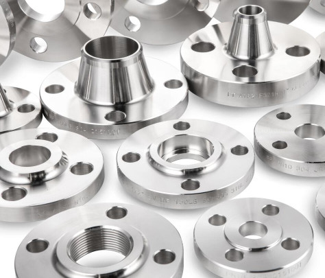
- Material Compatibility: The valve body and flange are typically made from forged or cast materials like carbon steel (A105N), stainless steel (F316), or ductile iron, chosen based on the operating environment (e.g., pressure, temperature, and media).
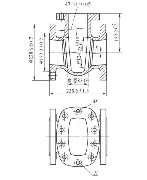
- Dimensional Precision: The seat bore must align perfectly with the gate to ensure a tight seal, while the flange dimensions must comply with ASME B16.5 for outer diameter (OD), pitch circle diameter (PCD), and gasket seating.
- Surface Finish: The seat bore requires a surface roughness of Ra 0.8–1.6 µm to ensure proper sealing, while the flange face typically needs Ra 3.2–6.3 µm for gasket compatibility.
- Pressure and Temperature Ratings: The design must accommodate pressure classes from 150 LB to 1500 LB and temperatures up to 500°C, depending on the application.
- Connection Types: Flanges may feature raised face (RF), flat face (FF), or ring-type joint (RTJ) configurations, with machining tailored to the specific type.
These specifications ensure the valve meets operational demands while maintaining compatibility with piping systems.
Machining Process for Integrated Seat Bore and Flange
The integrated machining process involves CNC (Computer Numerical Control) equipment to achieve high precision and repeatability. The process is divided into several stages, each addressing specific aspects of the seat bore and flange.
1. Material Preparation
Raw materials are inspected for defects using non-destructive testing (NDT) methods such as ultrasonic testing (UT) or X-ray examination. For forged steel valves, materials like A105N are preferred for their uniform grain structure. Cast materials, such as WCB or ductile iron, are used for larger valves. The material is cut to rough dimensions, ensuring sufficient stock for machining.
2. Rough Machining
Rough machining establishes the basic geometry of the valve body, seat bore, and flange. A CNC lathe is used to turn the outer and inner diameters of the valve body. The flange OD is machined to ASME B16.5 standards, with tolerances of ±0.5 mm for OD and ±0.2 mm for PCD. The seat bore is rough-turned to an oversized diameter (e.g., DN100 valve: ID 105 mm) to allow for finishing.
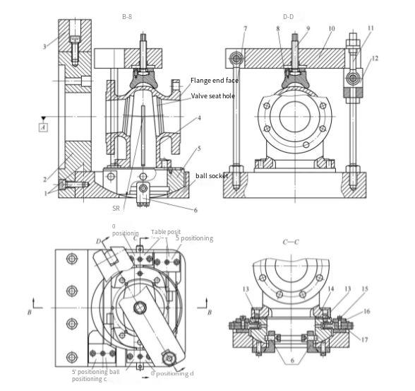
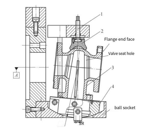
3. Integrated Machining Setup
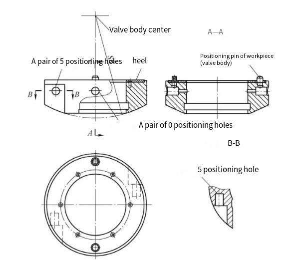
Integrated machining requires a single setup to machine both the seat bore and flange. This is achieved using a multi-axis CNC machine with a custom fixture to secure the valve body. The fixture ensures concentricity between the seat bore and flange, with alignment tolerances within 0.05 mm. The setup minimizes repositioning errors, ensuring that the seat bore’s centerline aligns with the flange’s bolt holes.
4. Precision Machining of Seat Bore
The seat bore is machined to its final dimensions using a boring tool. For a DN100 valve, the seat bore’s inner diameter is typically 102 mm ±0.02 mm, matching the pipe’s ID. The seat face is machined to a width of 10 mm per side, resulting in an outer diameter of 122 mm (102 mm + 2 × 10 mm). The surface finish is achieved using a carbide cutter, targeting Ra 0.8 µm for metal-seated valves or Ra 1.6 µm for resilient-seated designs. For high-pressure applications, the seat may be hardfaced with stellite to enhance wear resistance.
5. Flange Machining
The flange face is machined to match the specified configuration (RF, FF, or RTJ). For a raised face flange, the raised surface is machined to a height of 1.6 mm ±0.1 mm and a diameter matching the gasket size. Bolt holes are drilled with a tolerance of ±0.2 mm for PCD, ensuring alignment with mating flanges. The flange thickness is maintained at 18–24 mm, depending on the pressure class (e.g., Class 150: 18 mm; Class 600: 24 mm).
6. Finishing and Surface Treatment
After machining, the seat bore and flange undergo finishing processes such as grinding or polishing to achieve the required surface roughness. For corrosion resistance, the valve body may be coated with epoxy or subjected to passivation for stainless steel components. The flange face is cleaned to remove debris, ensuring proper gasket seating.
Key Design Parameters
The following table summarizes critical parameters for integrated machining of a DN100 gate valve seat bore and flange, based on a Class 150 rating:
| Component | Parameter | Flange OD | 178 mm ±0.5 mm |
|---|---|---|---|
| Flange Thickness | 18 mm ±0.2 mm | ||
| Bolt Hole PCD | 152.4 mm ±0.2 mm | ||
| Seat Bore | Inner Diameter | 102 mm ±0.02 mm | |
| Seat Width | 10 mm per side | ||
| Surface Roughness | Ra 0.8–1.6 µm |
Quality Control and Testing
Quality control is critical to ensure the machined components meet design specifications. Key procedures include:
- Dimensional Inspection: Use coordinate measuring machines (CMM) to verify tolerances for seat bore ID (±0.02 mm), flange OD (±0.5 mm), and PCD (±0.2 mm).
- Surface Roughness Testing: Employ profilometers to confirm Ra values for the seat bore (0.8–1.6 µm) and flange face (3.2–6.3 µm).
- Pressure Testing: Conduct hydrostatic tests at 1.5 times the rated pressure (e.g., 22.5 bar for Class 150) to verify sealing integrity.
- NDT: Perform UT or X-ray testing to detect internal defects in the machined components.
These tests ensure the valve meets standards like API 600 and ISO 5208 for leakage rates (e.g., Class A: no visible leakage).
Assembly and Installation Considerations
After machining, the gate valve is assembled with the gate, stem, bonnet, and other components. The gate is typically a wedge or parallel design, with wedge gates being common for high-pressure applications due to minimal seat wear. During installation, the following practices are critical:
- Flange Alignment: Ensure flanges are aligned within 0.05 mm to prevent stress on the valve body.
- Gasket Selection: Use gaskets compatible with the flange face (e.g., spiral-wound gaskets for RF flanges) to ensure a leak-free seal.
- Bolt Tightening: Tighten flange bolts in a cross-pattern sequence to achieve even pressure, with torque values per ASME PCC-1 (e.g., 70–100 Nm for M20 bolts).
- Orientation: Install the valve in an upright position for easy handwheel access, though horizontal installation is permissible if space is constrained.
Proper assembly and installation prevent issues such as misalignment or gasket failure, which could compromise the valve’s performance.
Maintenance and Service Life
Integrated machining enhances the valve’s service life by ensuring precise alignment and sealing. However, regular maintenance is required to sustain performance. Key maintenance tasks include:
- Periodic Inspection: Check the seat bore and gate for wear or erosion, especially in high-velocity or abrasive media applications.
- Lubrication: Apply lubricant to the stem threads to reduce operating torque and prevent seizing.
- Seat Refurbishment: For metal-seated valves, re-machine or replace seats if wear exceeds 0.5 mm to restore sealing integrity.
- Gasket Replacement: Replace flange gaskets during maintenance to prevent leakage, ensuring compatibility with the flange type.
With proper maintenance, a gate valve can achieve a service life of 10–20 years, depending on operating conditions.
Conclusion
The integrated machining of gate valve seat bore and flange is a critical process that ensures dimensional accuracy, sealing performance, and structural reliability. By adhering to precise design specifications, utilizing advanced CNC machining, and implementing rigorous quality control, manufacturers can produce high-quality gate valves suitable for demanding industrial applications. This systematic approach, supported by detailed parameters and professional execution, ensures the valve’s functionality and longevity, meeting the needs of industries such as oil and gas, water distribution, and chemical processing.