This article provides a comprehensive guide to the boring machining of multi-hole slotted blocks, focusing on addressing dimensional and geometric tolerance issues encountered during trial machining. It details an optimized machining process, including boring route selection, workpiece positioning, clamping methods, and step-by-step boring procedures. The content is based on practical experience with a specific part made of 40Cr2MoV, offering a systematic approach to ensure high precision and compliance with technical requirements.
Part Specifications and Initial Machining Issues
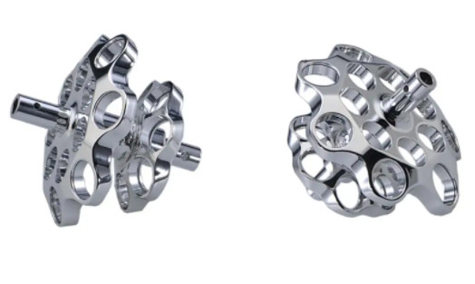
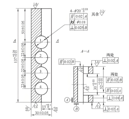
The multi-hole slotted block, used in marine diesel engines, is a rectangular forging made of 40Cr2MoV. The part features a central slot (137 mm long, 30 mm wide, 15 mm deep) on the front face and four φ20 mm through-holes on the side. The dimensional and geometric tolerances for the slot and holes are stringent, requiring precise machining to meet technical specifications. The initial trial machining process followed this sequence: rough and finish milling of the six faces, rough and finish milling of the slot, drilling, boring, and surface grinding. Inspection revealed that all four holes exhibited dimensional and geometric tolerance deviations, and the slot’s surface roughness and flatness failed to meet requirements.
Analysis identified several flaws in the initial process. Milling the slot before drilling and boring the holes led to coaxiality issues in the holes, as the slot’s presence reduced structural rigidity. This also compromised the slot’s surface roughness and flatness. Additionally, inadequate workpiece positioning, clamping, and boring sequence contributed to the failures. These issues necessitated a revised machining process to achieve the required precision.
Optimized Boring Route Selection
Choosing an appropriate boring route is critical to ensuring dimensional and geometric accuracy. For batch production, a distributed process route is recommended, while single-piece machining benefits from a centralized process route, where milling and drilling are performed on a boring machine. Two practical boring routes were developed to address the challenges of machining φ20 mm holes intersecting the slot, which can cause tool deflection and reduced hole accuracy.
- Route 1: Mill, Drill, Mill Slot, Bore
After rough and finish milling the six faces, drill four φ16 mm holes, mill the 30 mm wide slot, and then bore the holes to φ20 mm. This sequence ensures good rigidity during slot milling but requires additional measures during boring, such as adding a support wall at the hole’s rear to enhance system rigidity. However, adjusting the support wall and back-off amount during boring is complex and time-consuming. - Route 2: Mill, Drill, Bore, Mill Slot
After milling the six faces, drill and bore the four φ20 mm holes before milling the 30 mm slot. This avoids the issue of boring partial holes, ensuring better roundness and cylindricity. However, milling the slot last reduces system rigidity, requiring careful feed control near the hole centers to prevent deformation and maintain hole accuracy.
Route 2 was selected for its simplicity and ability to maintain hole precision, provided feed rates are carefully managed during slot milling. This approach eliminates the need for additional support structures, streamlining the process while achieving the required tolerances.
Workpiece Positioning and Clamping
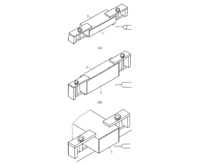
Accurate positioning and secure clamping are essential for consistent machining results. The rough milling process uses the 52 mm × 137 mm surface of the forging as the initial positioning datum. For milling the third face, a guide block is introduced, with the previously milled wide surface serving as the primary datum and another milled surface aligning with the guide block for stability.
Clamping is achieved using screw press plates applied at both ends of the workpiece’s flat surface. The clamping force must be reliable, aligned with support blocks, and avoid causing deformation or interfering with the machining surface. This setup ensures the workpiece remains stable during milling and boring, minimizing vibrations and positional errors.
Step-by-Step Boring Process
The boring process for the multi-hole slotted block is divided into several stages to ensure precision and repeatability. Each step is carefully planned to address the part’s geometric complexity and tolerance requirements.
Preparation and Workpiece Setup
Before boring, the machine table is inspected for flatness, and any protrusions are ground smooth. Guide rails and screws are cleaned and lubricated. The workpiece is placed on 50 mm high support blocks, lightly clamped with screw press plates, ensuring the clamping force passes through the blocks. Alignment is performed using a scriber to mark and verify the three faces, followed by milling the six faces. After clamping, a final alignment check ensures accuracy.
Rough and Finish Milling of Six Faces
The milling process begins with the forging’s wide surface as the datum. The sequence is as follows:
- Face 1 (Height): Mill using the wide surface as the datum.
- Face 2: Install two guide blocks on the table, aligned parallel to the cross-slide guide rail. Position Face 1 against the blocks, clamp, and mill Face 2.
- Face 3: Use Face 1 or 2 as the datum, align parallel to the cross-slide guide rail, and mill.
- Face 4: Follow the same method as Face 2.
- End Faces: Mill the two end faces, ensuring Face 1 or 2 is parallel to the spindle axis using a dial indicator.
Rough milling leaves a 2 mm allowance per face, followed by finish milling using the same sequence. A corn-tooth milling cutter with YT5 inserts is used. Machining parameters are detailed in the table below:
| Operation | Cutting Speed (v_c, m/min) | Feed Rate (v_f, mm/min) | Depth of Cut (a_p, mm) |
|---|---|---|---|
| Rough Milling | 60–80 | 300–600 | 0.5–4 |
| Finish Milling | >80 | 300–600 (lower range) | 0.5–4 (lower range) |
A 0.20 mm grinding allowance is left on the height faces to achieve the final dimensions.
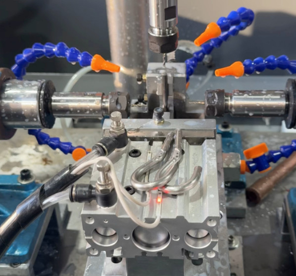
Drilling and Boring the Holes
The boring process begins with positioning using Face A (see part diagram) as the primary datum and Face B as the guide, aligned against a guide block. The clamping force is applied at the ends, avoiding the φ20 mm holes. The boring spindle’s position is determined using a centering mandrel and gauge blocks to calculate the spindle’s height and horizontal position relative to the workpiece.
The drilling and boring sequence is as follows:
- Center Drilling: Use a center drill to mark hole positions, with a minimal feed rate to ensure accuracy.
- Drilling φ16 mm Holes: Use a twist drill with a 120° point angle, shortened chisel edge (half the original length), 20° inner straight edge angle, and 15° rake angle, with chip-breaking grooves. Drilling parameters: spindle speed 350 rpm, feed rate 0.30 mm/rev.
- Boring to φ20 mm: Install a boring tool with YW1 inserts (main cutting angle 75° or 90°, secondary angle 8°, rake angle 14°, relief angle 6°, chip-breaking groove radius 2.5 mm, cutting depth 2 mm, negative chamfer angle -5°, chamfer width 0.1–0.3 mm, tool section ≥6 mm × 6 mm). Boring parameters are shown in the table below:
| Operation | Cutting Speed (v, m/min) | Feed Rate (f, mm/rev) | Depth of Cut (a_p, mm) |
|---|---|---|---|
| Semi-Finish Boring | 95 | 0.5 | 1.5, 1.0 |
| Finish Boring | 120 | 0.3 | 0.3 |
Subsequent holes are positioned using a chain-shift method, with precise table movement verified by a dial indicator and gauge blocks.
Slot Milling
The 30 mm wide slot is milled using a φ28 mm end mill, with the cutter center positioned 26 mm above the table. The workpiece’s wide face serves as the guide datum, aligned parallel to the cross-slide guide rail using a guide block. A thrust block is added at the workpiece’s end to prevent movement. Clamping avoids the slot area, with forces applied perpendicular to the table.
The slot is milled to a depth of 13 mm initially. Rough milling uses a feed per tooth of 0.08 mm/z and a cutting speed of 50 m/min. Finish milling refines the slot to 15+0.100 mm deep and 30+0.080 mm wide, using a feed per tooth of 0.06 mm/z and a cutting speed of 35 m/min. The process employs a trial-cut approach to gradually achieve the required dimensions, with cutting fluid applied to control heat and improve surface finish.
Final Grinding and Inspection
After boring and slot milling, the workpiece is transferred to a surface grinder to remove a 0.15 mm allowance from the height faces, achieving a surface roughness of Ra 0.8 μm. Comprehensive inspection confirms that the optimized process meets all dimensional and geometric tolerance requirements, including hole coaxiality, roundness, cylindricity, and slot flatness and roughness.
Conclusion
The optimized machining process for the multi-hole slotted block addresses the limitations of the initial trial process by revising the boring route, improving positioning and clamping, and implementing a systematic boring sequence. By drilling and boring the holes before milling the slot, and using precise positioning and controlled machining parameters, the process ensures high precision and reliability. The detailed steps and parameters provided offer a practical, repeatable approach for machining similar complex parts, ensuring compliance with stringent technical requirements.