In the automotive industry, the separation of design and manufacturing processes often leads to challenges in producing components that meet both design intent and manufacturability requirements. This article examines the role of auxiliary datums in compensating for design deficiencies, specifically in the machining of automotive engine brackets. Drawing on years of experience in automotive parts machining, this analysis focuses on a practical case study of a rear suspension bracket (part number B11-1001811) to illustrate the selection and application of auxiliary datums in mechanical machining processes.
Overview of Design and Manufacturing Disconnect
The automotive industry's shift toward a modular, specialized production model has resulted in a clear division between design and manufacturing. Companies at the upstream end of the supply chain focus on conceptual and structural design, while downstream manufacturers handle the physical production. This separation often leads to designs that, while theoretically sound, pose significant challenges during manufacturing due to a lack of consideration for machining processes. A common issue is the absence of suitable surfaces to serve as datum planes for positioning, necessitating the creation of auxiliary datums to ensure manufacturability.
An auxiliary datum is a surface or feature machined onto a workpiece to address deficiencies in the original design, such as inadequate or unreliable datum surfaces. These datums provide a stable and reliable reference for subsequent machining operations, mitigating the impact of design oversights on production efficiency and quality.
Case Study: Rear Suspension Bracket (B11-1001811)
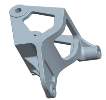
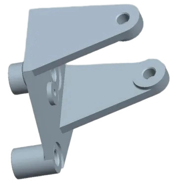
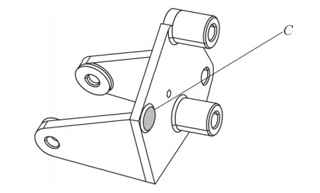
The rear suspension bracket (B11-1001811) is a cast iron component (material: QT450-10) used in automotive engine assemblies. The bracket undergoes metal mold casting, artificial aging (heating to 570–590°C, holding for 4 hours, cooling at 30°C/h to 250°C, and air cooling), shot blasting, and surface coating before entering the machining process. The bracket’s structure, as shown in its 3D model and dimensional drawings, includes four holes and eight surfaces requiring machining. The M-plane and its two φ12.5 mm holes serve as the design and measurement datums, ideally also functioning as the process datums.
The original machining process, outlined in the table below, was designed based on these datums:
| Operation | Description | Datum Used |
|---|---|---|
| OP10 | Machine M-plane and N-plane (height difference and thickness) | Non-machined surfaces |
| OP20 | Drill and ream 2×φ12.5 mm holes and 2×φ11 mm holes | M-plane, N-plane |
| OP30 | Machine additional surfaces | M-plane, 2×φ12.5 mm holes |
| OP40 | Milling of slotted surfaces | M-plane, N-plane, 2×φ12.5 mm holes, auxiliary support |
The initial process revealed significant limitations. While OP10 successfully machined the M-plane and N-plane, using the M-plane (φ28 mm) as a datum for subsequent operations was problematic due to its small surface area. The N-plane, with a height difference of 11.5 ± 0.2 mm relative to the M-plane, introduced variability in batch production, making it unreliable as a primary datum. The two φ28 mm planes (M and N) on the same side of the workpiece provided only two contact points, insufficient for stable positioning without an additional auxiliary point or surface.
In OP20 and OP40, the reliance on these datums led to unstable positioning, resulting in inconsistent machining dimensions and inability to sustain normal production. The root causes were twofold: first, the original design prioritized structural functionality over machining feasibility, neglecting the need for robust datum surfaces; second, the process engineers’ limited understanding of datum selection contributed to an impractical process plan.
Analysis of Datum-Related Issues
The challenges observed in the B11-1001811 bracket are not unique. Similar issues arise in other engine brackets, such as the front suspension bracket (T11-1001611MA) and another rear suspension bracket (T11-1001811MA). These components share a common problem: small datum surfaces or insufficient contact points. For instance, in cases where two lugs are coplanar (as in T11-1001611MA), they provide only two contact points, requiring one additional auxiliary surface for stable positioning. When lugs have a height difference (as in T11-1001811MA), only one contact point is available, necessitating two additional auxiliary points or surfaces.
In practice, adding auxiliary datums introduces risks, such as machining variations (e.g., repeatability errors or deformation). These risks are less pronounced in modern machining centers, which offer precise control, but remain significant for general-purpose equipment. Despite their functional simplicity, these brackets require careful process planning to ensure all machined features meet specifications.
Selection and Application of Auxiliary Datums
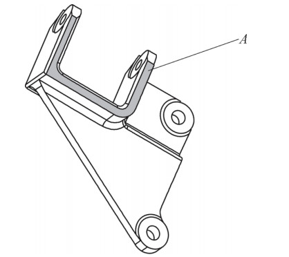
To address the datum deficiencies in the B11-1001811 bracket, process engineers selected a U-shaped surface (referred to as the A-plane) as the auxiliary datum. This surface was chosen for its larger contact and distribution area, which enhances positioning stability and supports higher cutting forces. The selection of auxiliary datums must consider three key questions:
- Which surface(s) should serve as the primary datum to achieve the required machining accuracy economically?
- Which surface(s) should be used as the rough datum to machine the primary datum?
- Are additional datums needed for specific operations?
Two fundamental requirements guide datum selection:
- Sufficient Machining Allowance: All machined surfaces must have adequate material to avoid defects like black spots, ensuring un-machined surfaces and wall thicknesses meet drawing specifications.
- Adequate Contact and Distribution Area: The datum surface must be large enough to withstand cutting forces and widely distributed to ensure stable and reliable positioning. If necessary, process bosses or auxiliary supports on fixtures can be added.
For the B11-1001811 bracket, the A-plane was machined in OP10 with minimal material removal (to “see light”) using non-machined Surfaces as rough datums. Subsequent operations used the A-plane as the primary datum, as shown in the revised process plan below:
| Operation | Description | Datum Used |
|---|---|---|
| OP10 | Machine A-plane (U-shaped surface, minimal cut) | Non-machined surfaces |
| OP20 | Turn two lug planes (M and N) | A-plane |
| OP30 | Drill and ream 2×φ12.5 mm holes | A-plane |
| OP50–OP80 | Machine additional surfaces and holes | A-plane, 2×φ12.5 mm holes |
Unlike the traditional “one plane, two holes” datum approach, this plan uses the A-plane as the sole primary datum, with the φ12.5 mm holes serving as secondary datums perpendicular to it. Since the A-plane is not a functional surface, it requires repainting after machining to restore its appearance. Trial and batch production confirmed the effectiveness of this process, achieving high dimensional accuracy, process stability, and efficiency.
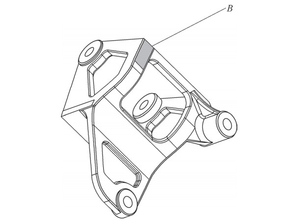
For the T11 brackets, similar auxiliary datums were selected (B and C planes), with the option to add small cast bosses (0.5–1.0 mm height) if permitted by the customer. These bosses, if retained, provide a permanent datum surface; otherwise, minimal machining ensures functionality.
Conclusion
The use of auxiliary datums effectively addresses design deficiencies in automotive engine bracket manufacturing, as demonstrated by the B11-1001811 rear suspension bracket. By carefully selecting and machining auxiliary datum surfaces, manufacturers can overcome challenges posed by inadequate design datums, ensuring stable positioning and consistent machining quality. While the optimal auxiliary datum varies by component and equipment, the principles outlined—prioritizing sufficient machining allowance and stable contact area—provide a reliable framework for process design. This approach, validated through practical application, offers valuable guidance for machining similar components, particularly in high-volume production using general-purpose equipment.