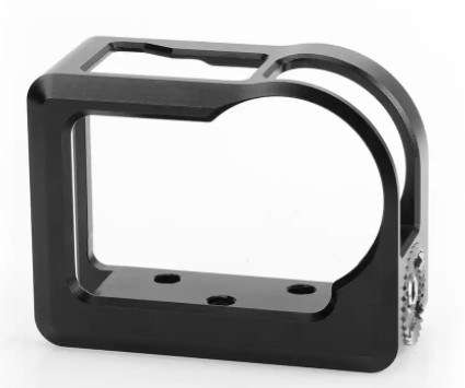
This document outlines the precision machining process for high-accuracy coaxial holes in titanium alloy camera brackets, emphasizing efficient, cost-effective, and high-quality production. The process addresses the challenges of machining thin-walled titanium alloy parts, ensuring dimensional accuracy and structural integrity through advanced techniques and deformation control measures.
Introduction to Camera Bracket Functionality
The camera bracket is a critical component in satellite camera systems, designed to securely mount the camera lens and enable 360-degree rotation. To meet operational and environmental requirements, the bracket must be lightweight yet possess high strength. Titanium alloy is selected for its high strength, corrosion resistance, high thermal stability, and relatively low density. The bracket features a thin-walled structure with a wall thickness of 4 mm, making it prone to deformation during clamping and machining, which can significantly impact precision.
Structural Characteristics and Technical Specifications
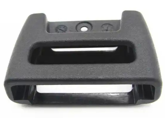
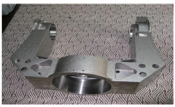
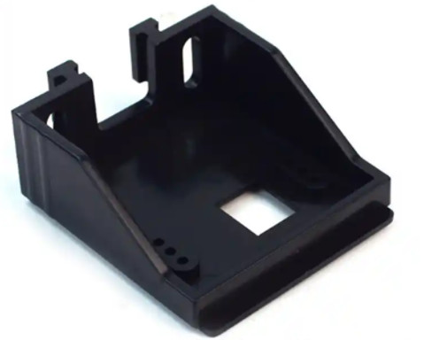
The camera bracket is a U-shaped component with external dimensions of 516 mm × 407 mm × 227 mm and a wall thickness of 4 mm. The majority of the structure consists of a cavity, contributing to its lightweight design. The component includes three critical holes, with two φ100 mm inner holes requiring a perpendicularity tolerance of 0.02 mm and a coaxiality tolerance of 0.01 mm across a 516 mm span. Additionally, the largest inner hole has a tolerance grade of IT4 and a depth of 80 mm, with a perpendicularity requirement of 0.02 mm relative to the φ100 mm hole axes.
Material Properties and Machining Challenges
Titanium alloy presents several machining challenges due to its material properties. Its low thermal conductivity results in high cutting temperatures, reducing tool life. The low deformation coefficient causes chips to slide extensively on the tool’s rake face, accelerating tool wear. The alloy’s low elastic modulus leads to bending deformation under radial cutting forces, causing vibrations that exacerbate tool wear and affect part accuracy. Additionally, titanium’s high chemical affinity with tool materials promotes adhesion and wear under high cutting temperatures and forces.
Process Flow Design
The machining process is divided into rough and finish machining stages, with intermediate heat treatments to minimize residual stresses and machining-induced hardening. The process flow is as follows:
- Rough milling of external contours.
- Stress-relief annealing to reduce internal stresses.
- Finish milling of external contours and internal cavities.
- Artificial aging combined with thermal cycling to stabilize the material.
- Boring of all inner holes in a single setup.
This structured approach ensures dimensional stability and reduces deformation impacts on precision.
Machining Difficulties
The following difficulties were identified during the machining of the titanium alloy camera bracket:
- Large Dimensions: The part’s size (516 mm × 407 mm × 227 mm) complicates machining due to the challenges of handling and maintaining precision over a large span.
- Thin-Walled Structure: The 4 mm wall thickness makes the part susceptible to deformation during clamping and machining.
- High-Precision Coaxial Holes: Achieving a coaxiality of 0.01 mm across a 516 mm span for the two φ100 mm holes is challenging.
- Tight Tolerances: The largest inner hole requires an IT4 tolerance grade with an 80 mm depth and a perpendicularity of 0.02 mm, demanding exceptional dimensional control.
Implemented Machining Solutions
To address these difficulties, the following measures were implemented to ensure precision and quality.
Equipment and Setup
A T4163 coordinate boring machine with a rotary table was selected to machine all holes in a single setup, minimizing errors from multiple clampings. The U-shaped bracket was clamped as shown in the referenced setup diagram, ensuring stability and accessibility for machining.
Inner Hole Dimensional Accuracy
To achieve the required roundness and dimensional stability, a dynamic balance boring head with diamond inserts was used. The two reference surfaces were finished on the boring machine with a single-edge tool and a cutting depth of 0.05 mm, achieving a flatness of 0.005 mm, close to the machine’s precision limit. The rotary table’s flipping accuracy, combined with auxiliary alignment methods, ensured the perpendicularity of 0.02 mm between the inner holes and reference surfaces. For finish boring, a 0.4 mm machining allowance was left, removed in multiple passes with equal material removal. Dimensional changes were monitored to adjust the removal amount, ensuring hole diameter accuracy and surface roughness requirements.
Deformation Control Measures
Deformation was controlled through the following approaches:
- Internal Stress Management: Rough and finish machining were separated by stress-relief annealing, artificial aging, and thermal cycling to minimize residual stresses.
- Clamping Deformation Control: Clamping forces were carefully managed using a multi-point dial indicator method. A three-point low-torque clamping approach was employed, with iterative tightening to maintain consistent dial indicator readings in the x and y axes, ensuring minimal deformation and uniform force distribution.
- Thermal Deformation Control: A water-soluble emulsion coolant was used to manage cutting temperatures, and the machining environment was maintained at 20 ± 2°C to minimize thermal deformation. Tool materials, angles, and cutting parameters were optimized to reduce cutting forces and associated deformations.
Coaxiality Assurance
To meet the 0.01 mm coaxiality requirement, a reference block was fixed on the rotary table as an auxiliary alignment datum. After machining one φ100 mm hole, the table was rotated 180° to machine the second hole. The rotation angle was verified using a dial indicator on the reference block to eliminate angular errors. An extended rod with a dial indicator was used to align the previously machined hole, ensuring coaxiality.
Vibration Control
Vibration was mitigated through two strategies:
- Forced Vibration Control: The machining setup was isolated from vibration sources to prevent resonance with other machines.
- Self-Excited Vibration Control: Tool rigidity, workpiece rigidity, and cutting forces were balanced by selecting appropriate tools, reducing cutting depth, lowering cutting speeds, optimizing feed rates, and enhancing tool rigidity to minimize vibrations and maintain geometric accuracy.
Quality Inspection Results
Post-machining, a coordinate measuring machine (CMM) was used to verify key technical specifications. All measured parameters met the design requirements. The key inspection results are summarized in the table below:
| Parameter | Requirement | Measured Value | Status |
|---|---|---|---|
| Coaxiality of φ100 mm Holes | 0.01 mm | 0.008 mm | Pass |
| Perpendicularity of φ100 mm Holes to Reference Surface | 0.02 mm | 0.015 mm | Pass |
| Largest Hole Tolerance (IT4) | IT4 Grade | Within IT4 | Pass |
| Reference Surface Flatness | 0.005 mm | 0.004 mm | Pass |
Conclusion
The machining process for the titanium alloy camera bracket successfully achieved high-precision coaxial holes while addressing the challenges of thin-walled structures and large dimensions. By employing a coordinate boring machine, single-setup machining, deformation control measures, and precise alignment techniques, the process ensured high accuracy, efficiency, and quality. The experience gained provides valuable insights for machining similar large-scale titanium alloy components, particularly in managing coaxiality and deformation in thin-walled parts.
