
Deep hole machining is a critical process in manufacturing hollow shaft components, such as those used in dual-clutch transmission (DCT) input outer shafts. However, tool vibration during this process often leads to dimensional inaccuracies, poor surface quality, and increased scrap rates. This article examines the causes of tool vibration in deep hole machining, using the trial production of DCT input outer shafts as a case study. It provides a systematic analysis of contributing factors, including tool geometry, tool holder materials, cutting parameters, and fixture design, and proposes effective solutions to mitigate vibration, improve part quality, and enhance production efficiency.
Overview of Deep Hole Machining and Tool Vibration
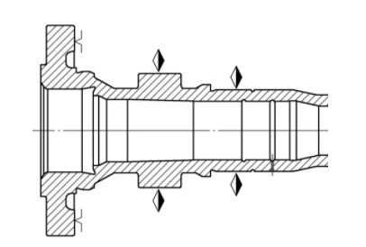
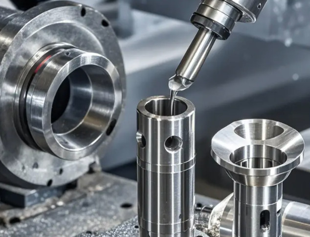
Deep hole machining involves creating holes with a depth-to-diameter ratio exceeding 5. In the trial production of DCT input outer shafts, deep hole boring is a critical yet challenging process due to tool vibration. This phenomenon causes unstable bore diameters and axial dimensions, compromising surface finish, increasing tool wear, and risking tool breakage. Traditionally, manufacturers reduce cutting parameters to minimize vibration, but this lowers efficiency. A comprehensive understanding of vibration causes and targeted solutions is essential to achieve high-quality machining without sacrificing productivity.
The trial production of DCT input outer shafts revealed that tool vibration during boring led to parts failing to meet dimensional tolerances, particularly in the oil seal bore (φ28.06 mm). This article analyzes the root causes of vibration and outlines practical measures to address it, focusing on tool selection, cutting parameters, and fixture design.
Causes of Tool Vibration in Deep Hole Machining
Tool vibration in deep hole machining results from a combination of environmental, mechanical, and operational factors. The following subsections detail the primary causes identified during the DCT input outer shaft trial production.
Semi-Closed Machining Environment
Deep hole machining occurs in a semi-closed environment, preventing direct observation of the cutting process. This limitation complicates monitoring of chip evacuation and heat dissipation. Accumulated chips can interfere with the cutting edge, causing tool chatter and inconsistent cutting forces. Poor heat dissipation may also lead to thermal deformation of the workpiece, further exacerbating vibration. Effective chip management and cooling strategies are critical to maintaining process stability.
Elastic Deformation of Tool Holder
Cutting forces during deep hole machining induce elastic deformation in the tool holder. When chips break off, the tool holder recovers, creating a cyclic boring force (F) that fluctuates sinusoidally. If this force’s frequency aligns with the tool holder’s natural frequency, resonance occurs, amplifying vibration. In deep hole machining, tool holders typically have a length-to-diameter ratio greater than 10, making them highly susceptible to elastic deformation and resonance. The choice of tool holder material and geometry plays a significant role in mitigating this issue.
Influence of Cutting Parameters
Cutting parameters, including spindle speed, feed rate, and depth of cut, directly affect cutting force stability. High spindle speeds increase cutting heat and noise, destabilizing the process. Excessive feed rates can cause poor chip breaking, leading to chip clogging, while an inappropriate depth of cut increases cutting forces, contributing to vibration. Optimizing these parameters is essential to balance part quality, tool life, and machining efficiency.
Impact of Tool Vibration on Part Quality
Tool vibration adversely affects part quality, leading to surface defects and dimensional inaccuracies. The following subsections describe the specific effects observed during the DCT input outer shaft machining process.
Surface Roughness and Defects
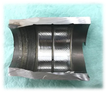
Vibration during deep hole boring results in poor surface finish, characterized by high roughness values and visible defects. Accumulated chips that are not evacuated promptly can scratch the bore surface, while vibration-induced relative motion between the tool and workpiece creates chatter marks or gouging. These defects often render parts non-reworkable, increasing scrap rates and production costs. In the DCT trial, surface scratches and chatter marks were prevalent, necessitating process adjustments.
Dimensional Inaccuracies
Tool vibration causes inconsistent cutting depths, leading to dimensional variations such as bore taper or misalignment. In the DCT input outer shaft trial, the oil seal bore (φ28.06 mm) exhibited diameter inconsistencies when machined with the same tool due to vibration. Table 1 summarizes measurement data from the trial, highlighting dimensional deviations caused by vibration, including bore diameter and coaxiality issues.
| Measurement Point | Specified Dimension (mm) | Actual Dimension (mm) | Deviation (mm) |
|---|---|---|---|
| Oil Seal Bore 1 | 28.06 ± 0.02 | 28.08 | +0.02 |
| Oil Seal Bore 2 | 28.06 ± 0.02 | 28.10 | +0.04 |
| Coaxiality | ≤ 0.03 | 0.05 | +0.02 |
Solutions to Mitigate Tool Vibration
Mitigating tool vibration requires a multi-faceted approach involving tool optimization, parameter adjustment, and fixture redesign. The following subsections detail the solutions implemented during the DCT input outer shaft trial production.
Optimizing Tool Selection
Selecting appropriate tools is critical for reducing cutting forces and vibration. The following considerations were applied:
- Tool Holder Material: Solid carbide or vibration-damping tool holders were chosen for their high stiffness and ability to absorb vibrational energy. These materials reduce elastic deformation under cutting forces, minimizing resonance risks.
- Main Cutting Angle (Kr): A 90° main cutting angle was selected to minimize radial cutting forces (Fp) while increasing axial forces (Ff), which are less likely to induce vibration in deep hole machining. This angle optimizes force distribution for stability.
- Tool Tip Radius (rs): A smaller tool tip radius of 0.4 mm (using DCMT inserts) was adopted to reduce cutting forces and improve chip formation, lowering the risk of vibration and enhancing chip evacuation.
- Blade Sharpness: Non-coated or physically coated (PCD) inserts were used due to their sharper edges compared to chemically coated (CVD) inserts. Sharper blades reduce friction and cutting forces, contributing to process stability.
Adjusting Cutting Parameters
Optimizing cutting parameters ensures stable machining and high part quality. The following adjustments were implemented:
- Spindle Speed (n): A spindle speed of 1300 rpm was selected to balance surface quality, tool life, and efficiency. This speed avoided excessive cutting heat and noise while preventing built-up edge formation on the tool.
- Feed Rate (f): A feed rate of 0.15 mm/rev was chosen to optimize chip formation and evacuation, reducing the risk of chip clogging and surface scratches.
- Depth of Cut (ap): The depth of cut was carefully controlled to limit cutting forces. A pre-machining step was introduced to ensure dimensional consistency before final boring, reducing the impact of vibration on dimensional accuracy.
Improving Fixture Design
Fixture design enhancements improve workpiece stability and reduce vibration. The following changes were implemented:
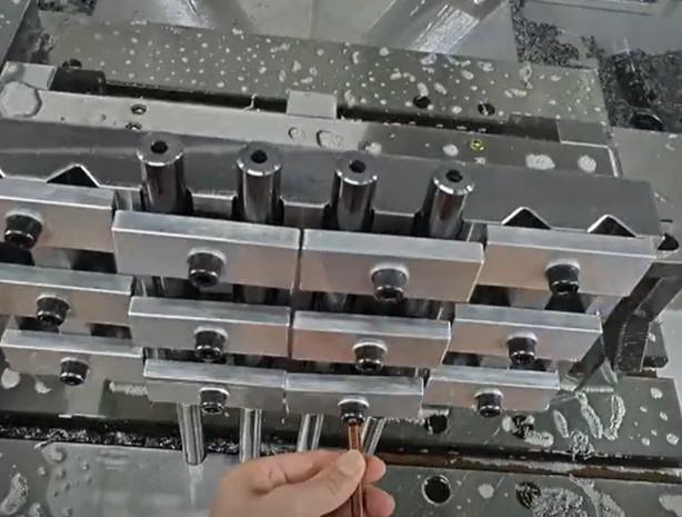
- Extended Clamping Jaws: Longer clamping jaws were used to support the hollow tail end of the workpiece, facilitating chip evacuation and reducing thermal deformation. This design minimized chip accumulation and overheating.
- Dual-Clamping Scheme: The original single-stop clamping, which used a short stop positioned far from the oil seal bore, was insufficient to prevent workpiece movement. The improved design adopted a 3+3 point dual-clamping setup, with the primary stop at the main clamping position and an additional stop at an adjacent outer diameter. This increased workpiece rigidity, minimized relative motion, and improved dimensional accuracy.
Implementation and Results
The proposed solutions were applied to the DCT input outer shaft trial production. A vibration-damping solid carbide tool holder with a 90° main cutting angle and a 0.4 mm tool tip radius (DCMT insert) was used. The spindle speed was set to 1300 rpm, with a feed rate of 0.15 mm/rev. A pre-machining step ensured coaxiality of the clamping stops, and the dual-clamping fixture design enhanced workpiece stability.
Post-implementation results showed significant improvements. The oil seal bore surface exhibited no visible chatter marks, and dimensional measurements confirmed that bore diameter, coaxiality, and surface roughness met specifications. Table 2 presents the measurement data for qualified parts, demonstrating the effectiveness of the solutions in eliminating vibration-related issues.
| Measurement Point | Specified Dimension (mm) | Actual Dimension (mm) | Deviation (mm) |
|---|---|---|---|
| Oil Seal Bore 1 | 28.06 ± 0.02 | 28.06 | 0.00 |
| Oil Seal Bore 2 | 28.06 ± 0.02 | 28.06 | 0.00 |
| Coaxiality | ≤ 0.03 | 0.02 | -0.01 |
The improved process reduced scrap rates and enhanced machining efficiency by minimizing adjustments and rework cycles. The oil seal bore’s surface quality was significantly improved, with no visible chatter marks or scratches, meeting all process requirements.
Conclusion
Tool vibration in deep hole machining of DCT input outer shafts is a critical issue that affects part quality and production efficiency. By analyzing the causes—semi-closed machining environments, tool holder elastic deformation, and suboptimal cutting parameters—and implementing targeted solutions, manufacturers can significantly reduce vibration. Optimizing tool selection (solid carbide tool holders, 90° main cutting angle, 0.4 mm tool tip radius), adjusting cutting parameters (1300 rpm, 0.15 mm/rev feed rate), and improving fixture design (dual-clamping scheme) resulted in enhanced surface quality, dimensional accuracy, and reduced scrap rates. These findings provide a practical framework for addressing tool vibration in deep hole machining applications, ensuring high-quality production and improved efficiency.