
Deep blind hole machining remains a significant technical challenge in the precision manufacturing industry, particularly for components requiring high dimensional accuracy and stringent geometric tolerances. This article presents a novel machining process for deep blind hole bearing seats in high-speed, long-life electric motors. By integrating five-axis CNC grinding with online measurement, the proposed method addresses key difficulties in achieving precise inner hole dimensions, geometric tolerances, and surface quality. The process was developed through experimental trials and applied to a specific bearing seat component, demonstrating improved reliability, efficiency, and consistency compared to traditional methods.
Component Characteristics and Machining Difficulties
The bearing seat discussed in this study is a critical component in a high-speed electric motor, designed to secure internal parts under demanding operational conditions. The component is made from 9Cr18Mo stainless steel, heat-treated to a hardness of 48–53 HRC. It features a cavity structure with thin walls and a flat end face as the reference surface. The primary machining focus is the inner hole, which has a depth of 70 mm and a retraction groove width of 2.6 mm. The inner hole must meet stringent requirements, including:
- Perpendicularity between the end face and inner hole: ≤0.002 mm
- Inner hole roundness: ≤0.002 mm
- Inner hole straightness: ≤0.002 mm
These precision requirements pose significant machining difficulties due to the deep blind hole’s geometry and the material’s high hardness. Traditional machining methods struggle to maintain dimensional accuracy and geometric tolerances, often resulting in issues such as excessive taper and inconsistent surface quality.
Original Machining Process and Its Limitations
The original process for machining the inner hole of the bearing seat involved the following steps:
- Positioning the workpiece using the outer diameter as a reference and clamping it with an electromagnetic centerless fixture.
- Rough grinding the inner hole.
- Fine grinding the inner hole using the end face as a reference.
- Manual polishing to achieve final precision.
While this process could eventually meet design requirements, it faced several limitations that impacted efficiency and quality:
- Measurement Challenges: Conventional gauges could not measure the deep blind hole effectively, requiring offline inspection with a coordinate measuring machine (CMM) and an extended probe. This process was time-consuming and sensitive to temperature variations, making it unsuitable for in-process measurements.
- Taper and Dimensional Errors: The deep blind hole’s depth caused uneven grinding wheel wear, with greater wear at the wheel’s front end. Radial cutting forces also caused deflection in the grinding spindle, leading to taper errors (≥0.01 mm) that exceeded tolerance limits.
- Manual Polishing Dependency: Achieving the required precision relied heavily on manual polishing with a 0.02 mm allowance. This step was labor-intensive, taking approximately 2 hours per part, and required an additional 4 hours of constant-temperature inspection. Manual polishing also introduced inconsistencies, such as bell-mouthing or scratches, which compromised straightness and surface quality.
Improved Machining Process
To address the limitations of the original process, a new machining method was developed, leveraging a high-speed five-axis CNC machining center (maximum spindle speed: 20,000 rpm) combined with online measurement and intelligent correction technologies. The improved process enhances precision, reduces manual intervention, and increases efficiency.
Equipment Selection
The five-axis CNC machining center was selected for its ability to meet the stringent surface roughness and geometric tolerance requirements. The machine enables precise control of the grinding process by aligning the inner hole axis perpendicular to the reference end face. A cubic boron nitride (CBN) grinding wheel with a thickness of less than 2.6 mm is mounted on the tool holder for cylindrical grinding. Online measurement and correction technologies automatically detect the reference surface, reconstruct the machining coordinate system, and eliminate errors caused by datum transfer. This approach minimizes the need for multiple fixtures, shortens production cycles, and reduces manufacturing costs.
Machining Principle
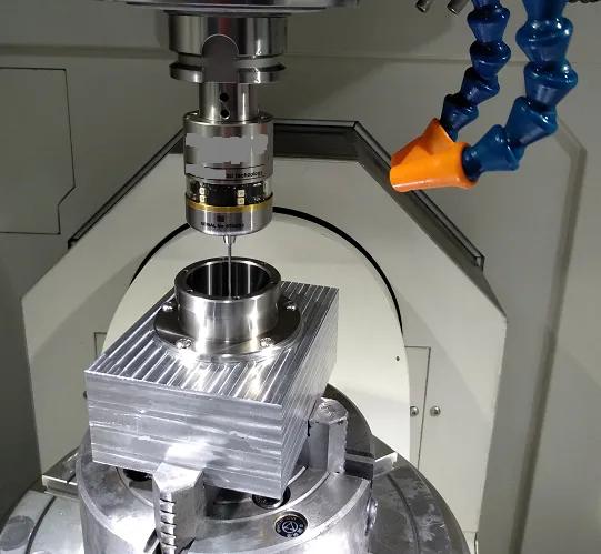
The improved process uses a programmed machining sequence integrated with an online measurement macro. The workflow is as follows:
- An inductive probe is mounted on the tool holder and moved to contact the workpiece, recording coordinate values upon contact.
- Multiple contact points are used to reconstruct the workpiece’s contour, and the data is fed into the machining program for automatic compensation.
- The reference plane is leveled using a three-point method, ensuring the Z-axis coordinates of three contact points are identical, thus aligning the plane perpendicular to the spindle.
- Initial calibration determines dimensional deviations, which are used to adjust cutting parameters for subsequent operations.
This process enables automated measurement and compensation, allowing the workpiece to be machined in a single setup with no manual intervention, ensuring consistent quality.
Clamping Method
Conventional clamping methods exerted excessive force, causing deformation and machining errors. To mitigate this, a step-fixed clamping method was adopted, utilizing the outer ring structure to secure the workpiece. This approach minimizes deformation while maintaining dimensional and geometric accuracy.
Process Flow
The optimized process consists of the following steps:
- Rough grinding the inner hole using the outer diameter as a reference.
- Fine grinding the inner hole using the end face as a reference, leaving a 0.03 mm allowance and controlling taper to ≤0.01 mm.
- Clamping the workpiece using the step-fixed method.
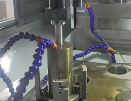
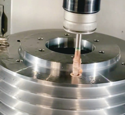
- Rough finishing the inner hole on the five-axis CNC machine.
- Fine finishing the inner hole with automated adjustments based on online measurements.
The fine grinding step uses an internal cylindrical grinder to prepare the inner hole, while the finishing steps employ the five-axis CNC machine. To address taper issues, the finishing process is divided into rough and fine finishing. Rough finishing uses a coarser CBN grinding wheel with a higher feed rate to improve efficiency and reduce taper. Fine finishing uses a finer wheel to achieve precise dimensions, surface roughness, and minimal taper. The grinding wheel, 2 mm thick, oscillates vertically during high-speed rotation, following a circular trajectory to ensure uniform material removal.
Processing parameters for rough and fine finishing are detailed in the table below:
| Process | Grinding Wheel Grit | Feed Rate (mm/min) | Spindle Speed (rpm) | Depth of Cut (mm) |
|---|---|---|---|---|
| Rough Finishing | Coarser (e.g., 80#) | 100–150 | 15,000–18,000 | 0.015–0.02 |
| Fine Finishing | Finer (e.g., 120#) | 50–80 | 18,000–20,000 | 0.005–0.01 |
The process includes three rough finishing passes with one online measurement and one fine finishing pass with another measurement, resulting in a total machining time of approximately 95 minutes—significantly less than the original process’s combined polishing and inspection time.
Performance Comparison
The new process was compared to the original method through surface quality and dimensional accuracy assessments. The original process produced inner hole surfaces with axial and circumferential polishing marks, visible under 40x magnification as fine, irregular textures. In contrast, the new process resulted in axial streak patterns with consistent, pronounced textures, indicating improved surface uniformity.
Dimensional accuracy was evaluated by measuring the inner hole diameter at various depths. The results, shown in the table below, confirm that both online and CMM measurements meet design requirements, with a cylindricality deviation of 0.0002 mm between the two methods.
| Depth (mm) | Original Process Diameter (mm) | New Process Diameter (mm) | Design Requirement (mm) |
|---|---|---|---|
| 10 | 20.002 | 20.001 | 20.000 ± 0.002 |
| 30 | 20.003 | 20.001 | 20.000 ± 0.002 |
| 50 | 20.004 | 20.002 | 20.000 ± 0.002 |
Surface roughness measurements showed that the original process achieved slightly better results (Ra ≈ 0.1 μm) compared to the new process (Ra ≈ 0.15 μm). However, both methods met the design requirements (Ra ≤ 0.2 μm), with the new process offering superior consistency and reduced processing time.
Conclusion
The proposed machining method, utilizing a five-axis CNC machining center with online measurement and intelligent correction, effectively addresses the challenges of deep blind hole machining for motor bearing seats. Key outcomes include:
- Stable and reliable dimensional accuracy and geometric tolerances, meeting stringent design requirements.
- Significant improvement in machining efficiency, reducing processing time from over 6 hours (including polishing and inspection) to approximately 95 minutes.
- Elimination of manual polishing, minimizing human-induced variability and surface defects.
- Automated single-setup machining, ensuring consistent quality and reduced production costs.
This method provides a practical and efficient solution for high-precision deep blind hole machining, suitable for applications requiring exceptional accuracy and reliability.