
Aluminum alloys, particularly 7075, are widely used in aerospace, automotive, and defense industries due to their high strength and excellent mechanical properties. Square frames, as critical structural components in applications like unmanned aerial vehicle (UAV) camera systems, demand stringent precision and minimal deformation. This article outlines a systematic machining process to control and eliminate deformation in aluminum alloy square frames, focusing on a practical case study of a UAV camera frame. The approach emphasizes process planning, tooling design, and precision machining to meet high geometric tolerances and surface quality requirements.
Structural Features and Technical Challenges
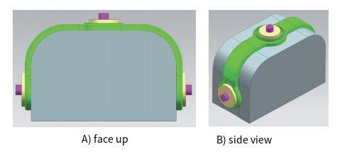
The square frame serves as the primary structural carrier in a UAV’s precision rotating camera system. It is a thin-walled component made of 7075 aluminum alloy with a wall thickness of 3 mm. The frame must maintain high geometric tolerances, including horizontal and vertical through-holes with a surface roughness of Ra 1.6 μm. The key technical challenges include:
- High Precision Requirements: The frame’s horizontal and vertical through-holes and end faces require tight geometric tolerances, critical for the camera’s functionality.
- Thin-Walled Structure: The 3 mm wall thickness makes the frame prone to deformation during machining due to low rigidity.
- Material Properties: 7075 aluminum alloy, while strong, is susceptible to internal stress accumulation, which can lead to deformation if not managed properly.
- Deformation Control: Balancing precision machining with deformation control is critical, as excessive material removal or improper clamping can distort the frame.
Machining Process Design
The machining process for the square frame is designed to minimize deformation while achieving the required precision. The process involves multiple stages, including rough machining, stress relief, and precision finishing, supported by custom tooling to enhance rigidity.
First Rough Machining
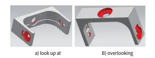
The initial stage involves removing large amounts of material from the raw square blank to form an open-structure rough blank. This step is critical for releasing internal stresses early in the process.
- Process Details: The U-shaped inner cavity is machined with a 0.5 mm allowance on each side. The open structure prevents stress concentration that could occur in a closed blank, which might lead to deformation upon cutting.
- Objective: Remove excess material to allow initial stress release while maintaining sufficient material for subsequent machining.
Second Rough Machining
The second roughing stage refines the blank, machining low-precision areas to final dimensions and preparing high-precision areas for finishing.
- Step 1: Perform finish cutting (light machining) on the four sides and U-shaped inner cavity to reduce rough machining-induced deformation, leaving a 0.4 mm allowance in the cavity.
- Step 2: Machine the red groove area (as shown in the reference diagram) to its final dimensions without allowance.
- Step 3: Rough machine three sets of sleeve holes, leaving a 0.2 mm allowance per side.
- Analysis: The blank retains sufficient rigidity for clamping, and the reduced machining allowance minimizes deformation in subsequent steps.
Third Rough Machining
Wire electrical discharge machining (WEDM) is used to remove excess material from the outer profile, leaving craft lugs on both sides for clamping.
- Process Details: WEDM minimizes heat generation, reducing thermal deformation compared to traditional cutting methods.
- Objective: Shape the outer profile while preserving material for clamping in later stages.
Stress Relief Treatment
After rough machining, the workpiece undergoes a stress relief heat treatment to stabilize its microstructure and eliminate internal stresses.
| Parameter | Value |
|---|---|
| Initial Temperature | Room Temperature |
| Heating Rate | 127°C/h |
| Holding Temperature | 185 ± 10°C |
| Holding Time | 4–5 hours |
| Cooling Rate | 43°C/h |
| Cooling Method | Furnace Cooling |
| Final Temperature | Room Temperature |
Analysis: This treatment stabilizes the material, reducing the risk of deformation during subsequent precision machining.
Datum Precision Machining
To address the low rigidity of the open-structure blank, a closed pseudo-blank is created to enhance stability during datum machining.
- Step 1: Machine four pin holes on the front face of the blank and a matching connection block. Connect the blank and block using pins to form a closed pseudo-blank.
- Step 2: Use a pressure plate to clamp the pseudo-blank and finish the upper plane (including craft lugs and connection block) to create a reference plane.
- Step 3: Flip and clamp the pseudo-blank to finish the opposite plane and machine the U-shaped cavity, leaving a 0.05 mm allowance.
- Step 4: Disassemble the pseudo-blank to release machining stresses, then clamp the craft lugs in a vise to enlarge the pin holes on the blank’s end face.
- Step 5: Similarly, enlarge the pin holes on the connection block, reconnect the pseudo-blank, and repeat steps 2 and 3 to finish the four-sided datum and U-shaped cavity.
- Results: After the first disassembly, deformation and shrinkage were 0.03 mm; after the second, only 0.005 mm, demonstrating effective stress control.
- Analysis: The closed pseudo-blank enhances rigidity, mitigating deformation from open-structure machining. Iterative stress release minimizes residual stresses.
Precision Machining of Sleeve Holes and End Faces
With the datum established, the three sleeve holes and their corresponding end faces are machined to final dimensions.
- Process Details: Clamp the workpiece in a vise along the thickness direction, ensuring full contact with the craft lugs and connection block. Align the datum within 0.005 mm, then machine the sleeve holes and end faces in the sequence: datum alignment → rough boring → position inspection → finish boring.
- Inspection: Use a high-precision probe for real-time position verification.
- Analysis: High-precision five-axis CNC machines with rotational accuracy of 0.005–0.01 mm are ideal but rare. The sequential approach ensures accuracy without relying on such equipment.
Removal of Craft Lugs
WEDM is used again to remove the craft lugs, leaving a 0.2 mm allowance per side to minimize deformation.
Analysis: The low heat input of WEDM ensures minimal impact on the workpiece’s stability.
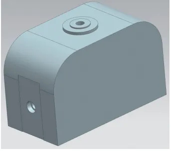
Final Contour Milling
A custom internal support fixture is used to enhance rigidity during final contour milling to achieve the required dimensions.
- Process Details: The fixture fills the internal cavity, preventing deformation during milling. The outer contour is machined with a single-side allowance of ≤0.3 mm.
- Analysis: The high strength of 7075 aluminum ensures material stability, and the small allowance reduces deformation risk. The internal fixture maintains structural integrity during machining.
Process Outcomes
The described process successfully controls deformation in the aluminum alloy square frame, achieving the required geometric tolerances and surface roughness (Ra 1.6 μm). Key outcomes include:
- Deformation Control: Iterative roughing, stress relief, and pseudo-blank techniques reduced deformation to 0.005 mm in critical stages.
- Precision Achievement: The sequential machining and high-precision inspection ensured compliance with tight tolerances.
- Material Stability: The properties of 7075 aluminum, combined with stress relief, supported consistent machining outcomes.
Conclusion
The machining of aluminum alloy square frames for UAV camera systems requires careful process planning to control deformation while meeting stringent precision requirements. By implementing staged roughing, stress relief, custom tooling, and precision finishing, the process effectively addresses the challenges of thin-walled structures and high-strength materials. This systematic approach ensures high accuracy and minimal deformation, providing a reliable framework for similar aluminum alloy components in aerospace and other industries.