Polyetheretherketone (PEEK) is a high-performance thermoplastic prized for its mechanical strength, chemical resistance, and thermal stability, making it ideal for precision components in aerospace, medical, automotive, and electronics industries. Machining PEEK, however, requires specialized techniques due to its unique properties. This guide provides a detailed, technical overview of PEEK machining processes, material types, and challenges, with precise parameters to ensure optimal results.
Understanding PEEK Material Properties
PEEK is a semi-crystalline polymer with a melting point of approximately 343°C and a glass transition temperature of 143°C. Its tensile strength ranges from 90–100 MPa for unfilled grades and up to 170 MPa for reinforced grades. PEEK’s low thermal conductivity (0.25 W/m·K) and high chemical resistance make it suitable for harsh environments, but these properties also influence machining strategies. Understanding these characteristics is critical for selecting appropriate tools and parameters.
Types of PEEK Materials
PEEK is available in various grades, each tailored for specific applications. The choice of PEEK type affects machining approaches due to differences in hardness, wear resistance, and thermal behavior. Below are the primary types of PEEK used in machining:
| PEEK Type | Composition | Key Properties | Applications | Machining Considerations |
|---|---|---|---|---|
| Unfilled PEEK | Pure PEEK resin | High purity, excellent chemical resistance, moderate strength (90–100 MPa) | Medical implants, seals, electrical insulators | Softer, easier to machine, prone to burrs |
| Glass-Filled PEEK | PEEK with 10–30% glass fiber | Increased stiffness (up to 10 GPa modulus), improved creep resistance | Structural components, aerospace parts | Abrasive, requires diamond tools, generates heat |
| Carbon-Filled PEEK | PEEK with 10–30% carbon fiber | Higher strength (up to 170 MPa), enhanced wear resistance | Bearings, gears, high-load parts | Highly abrasive, demands robust tools, precise cooling |
| Bearing-Grade PEEK | PEEK with PTFE, graphite, or carbon additives | Low friction, self-lubricating, high wear resistance | Bushings, wear pads | Complex composition, requires sharp tools, minimal heat |
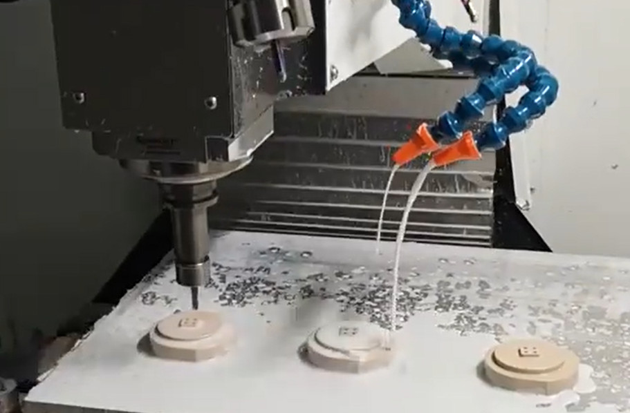
PEEK Machining Process Guide
Machining PEEK involves subtractive processes like CNC milling, turning, and drilling. Each step requires precise control to maintain dimensional accuracy and surface quality. Below is a detailed guide to the machining process.
Material Preparation (Annealing)
Annealing relieves residual stresses in extruded PEEK, preventing cracking or warping during machining. The process involves:
- Heating: Raise the material to 200–220°C for 1–2 hours, depending on thickness (approximately 30 minutes per 10 mm).
- Cooling: Cool slowly at 10–20°C per hour to room temperature to enhance crystallinity and dimensional stability.
- Intermediate Annealing: For long machining runs, re-anneal parts to maintain stability, especially for tight tolerances (±0.01 mm).
Tool Selection
Tool choice depends on the PEEK grade:
- Unfilled PEEK: Use sharp, polished silicon carbide (SiC) or fine-grain carbide tools. Cutting edge radius should be 0.01–0.02 mm to minimize burrs.
- Reinforced PEEK: Employ polycrystalline diamond (PCD) tools for glass- or carbon-filled grades due to their abrasiveness. Tool life for carbide tools drops significantly (50–70% reduction) with reinforced PEEK.
- General Guidelines: Maintain sharp edges (rake angle 10–15°, clearance angle 5–10°) to reduce heat buildup and ensure clean cuts.
Machining Parameters
Optimal parameters vary by PEEK type and machining process. Below are recommended settings for CNC milling and turning:
| Process | PEEK Type | Cutting Speed (m/min) | Feed Rate (mm/rev or mm/tooth) | Depth of Cut (mm) | Coolant |
|---|---|---|---|---|---|
| Milling | Unfilled | 150–300 | 0.05–0.15 | 0.5–2.0 | Air or minimal water-based |
| Milling | Glass/Carbon-Filled | 100–200 | 0.03–0.10 | 0.3–1.5 | Compressed air |
| Turning | Unfilled | 200–400 | 0.1–0.3 | 0.5–3.0 | Air or minimal water-based |
| Turning | Glass/Carbon-Filled | 100–250 | 0.05–0.2 | 0.3–2.0 | Compressed air |
Note: Avoid excessive coolant to prevent stress cracking in unfilled PEEK. Use compressed air or minimal water-based coolant for heat dissipation.
Drilling and Tapping
Drilling PEEK requires careful parameter control:
- Drill Geometry: Use twist drills with a 90–118° point angle and high helix angle (30–40°) to reduce heat and chip evacuation issues.
- Speed and Feed: For unfilled PEEK, use 50–100 m/min cutting speed and 0.05–0.15 mm/rev feed rate. Reduce by 20–30% for reinforced grades.
- Tapping: Use taps with a 15° rake angle and lubricate sparingly to avoid material adhesion. Peck tapping (incremental depth) prevents chip clogging.
Post-Machining
Post-machining processes ensure dimensional accuracy and surface quality:
- Deburring: Use ceramic deburring tools or abrasive nylon brushes to remove burrs, especially on unfilled PEEK.
- Surface Finishing: Achieve surface roughness (Ra) of 0.4–0.8 µm with polishing or fine milling passes.
- Inspection: Use CMM (Coordinate Measuring Machine) for dimensional checks, targeting tolerances as tight as ±0.01 mm for critical parts.
Difficulties in PEEK Machining
While PEEK is machinable, its properties present specific challenges that require careful management to achieve high-quality results.
Heat Generation and Thermal Management
PEEK’s low thermal conductivity causes heat to accumulate at the cutting zone, potentially leading to material softening (above 143°C) or tool wear. Reinforced grades exacerbate this due to their abrasiveness. Mitigation includes:
- Using lower cutting speeds (100–200 m/min for reinforced PEEK).
- Employing compressed air or minimal coolant to dissipate heat without inducing stress cracks.
- Monitoring tool temperature with infrared sensors to avoid exceeding 200°C.
Tool Wear and Material Abrasiveness
Glass- and carbon-filled PEEK grades are highly abrasive, reducing tool life by 50–70% compared to unfilled PEEK. PCD tools are recommended, but their cost is 3–5 times higher than carbide. Strategies to minimize wear include:
- Using high-quality, sharp tools with optimized geometries.
- Reducing feed rates (0.03–0.10 mm/tooth for milling reinforced PEEK).
- Regular tool inspection and replacement after 50–100 minutes of continuous machining.
Burr Formation
Unfilled PEEK is prone to burrs due to its ductility, particularly in milling and drilling. To minimize burrs:
- Use sharp tools with a small cutting edge radius (0.01–0.02 mm).
- Implement climb milling instead of conventional milling to reduce exit burrs.
- Apply post-machining deburring with non-abrasive tools.
Dimensional Stability
Residual stresses in PEEK can cause warping or dimensional deviations post-machining, especially for thin-walled parts (≤2 mm). Annealing is critical, and additional measures include:
- Using fixtures to secure parts during machining.
- Avoiding excessive clamping pressure to prevent deformation.
- Machining in multiple light passes to minimize stress buildup.
Best Practices for PEEK Machining
To achieve consistent results, follow these best practices:
- Pre-Machining: Always anneal PEEK stock to relieve stresses, especially for tolerances tighter than ±0.05 mm.
- Tool Maintenance: Inspect tools frequently for wear, particularly when machining reinforced PEEK.
- Parameter Optimization: Start with conservative speeds and feeds, then adjust based on tool wear and surface quality.
- Environment Control: Maintain a clean machining environment to prevent contamination, critical for medical-grade PEEK.
- Documentation: Record parameters and tool life data to optimize future runs, especially for high-volume production.
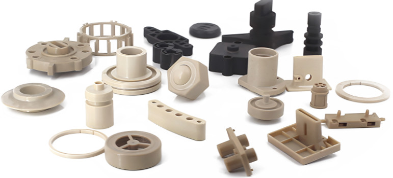
Applications of Machined PEEK Components
Machined PEEK components are used in:
- Aerospace: Lightweight, high-strength parts like brackets and insulators.
- Medical: Biocompatible implants and surgical instruments.
- Automotive: Durable seals and bushings for high-temperature environments.
- Electronics: Insulating components for high-voltage applications.
Precision machining ensures these parts meet stringent dimensional and performance requirements.
Conclusion
Machining PEEK requires a thorough understanding of its material properties, careful process planning, and precise execution. By selecting appropriate tools, optimizing parameters, and addressing challenges like heat generation and tool wear, manufacturers can produce high-quality PEEK components for demanding applications. This guide provides the technical foundation to achieve consistent, reliable results in PEEK machining.