Precision machining represents the pinnacle of manufacturing accuracy, utilizing computer numerical control (CNC) technology to produce components with exceptionally tight tolerances and superior surface finishes. This comprehensive manufacturing process combines advanced cutting tools, precise parameter control, and sophisticated equipment to create parts that meet the demanding specifications required in aerospace, medical, automotive, and defense industries.
What is Precision Machining
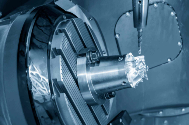
Precision machining is a subtractive manufacturing process that uses computer-controlled machine tools to remove material from a workpiece with exceptional accuracy. This process achieves dimensional tolerances typically within ±0.005 inches (±0.127 mm) and can produce complex geometries that would be impossible with conventional machining methods.
The process relies on two fundamental components: high-precision cutting tools capable of removing material with microscopic accuracy, and Computer Numerical Control (CNC) machines that automatically direct tool movement based on programmed instructions. This combination enables manufacturers to produce parts with consistent quality, tight tolerances, and excellent repeatability across production runs.
Unlike traditional machining methods, precision machining utilizes advanced CAD/CAM software to convert three-dimensional designs into precise toolpath instructions. The G-code and M-code programming languages control tool coordinates and auxiliary machine functions, ensuring that every cut, drill, and surface finish meets exact specifications.
Key Characteristics of Precision Machining
- ✔ Tolerances within ±0.005 inches (±0.127 mm)
- ✔ Surface roughness values from Ra 0.1 to 0.4 µm
- ✔ Computer-controlled automation for consistency
- ✔ Complex geometries and intricate features
- ✔ High repeatability across production volumes
Critical Precision Machining Parameters
Successful precision machining depends on careful control of multiple parameters that directly influence part quality, tool life, and manufacturing efficiency. These parameters must be optimized for specific material properties, cutting tool characteristics, and desired surface finish requirements.
Spindle Speed and Cutting Speed
Spindle speed, measured in revolutions per minute (RPM), determines the rotational velocity of the cutting tool. Cutting speed represents the linear velocity at which the tool edge contacts the workpiece surface, typically measured in surface feet per minute (SFM) or meters per minute.
Optimal spindle speeds vary significantly by material: aluminum allows 3000-6000 RPM, while hardened steel requires 500-1500 RPM. The relationship between spindle speed and cutting speed follows the formula: Cutting Speed = π × Diameter × RPM.
Feed Rate and Plunge Rate
Feed rate controls how quickly the cutting tool advances through the material, measured in inches per minute (IPM) or millimeters per minute. Plunge rate specifically governs vertical tool movement when entering the workpiece.
Proper feed rates balance material removal efficiency with surface finish quality. Higher feed rates increase productivity but may compromise surface finish, while lower rates improve finish quality but extend machining time.
| Material Type | Spindle Speed (RPM) | Feed Rate (IPM) | Depth of Cut (inches) |
|---|---|---|---|
| Aluminum | 3000-6000 | 100-300 | 0.040-0.100 |
| Carbon Steel | 1500-3000 | 50-150 | 0.020-0.080 |
| Stainless Steel | 1000-2000 | 30-100 | 0.010-0.050 |
| Titanium | 500-1500 | 20-80 | 0.010-0.040 |
| Acrylic Plastic | 10000-16000 | 150-400 | 0.020-0.100 |
Depth of Cut
Controls material removal thickness per pass. Typical ranges: 0.5-2.0mm for soft materials, 0.1-0.5mm for hardened steels. Affects tool load and surface finish quality.
Chip Load
Material removed per cutting edge per revolution. Optimized chip load prevents tool wear and ensures effective material removal without generating excessive heat.
Coolant Flow
Essential for heat dissipation and chip evacuation. Proper coolant application extends tool life and improves surface finish in precision applications.
Precision Machining Processes and Methods
Precision machining encompasses multiple specialized processes, each designed to achieve specific geometric features and surface finish requirements. These methods can be combined within multi-axis machining centers to produce complex components in single setups, reducing handling errors and improving dimensional accuracy.
CNC Milling Operations
CNC milling utilizes rotating multi-point cutting tools to remove material from stationary workpieces. Modern milling centers offer 3, 4, and 5-axis capabilities, enabling complex contour machining, precise hole drilling, and intricate pocket milling operations.
High-speed milling techniques achieve excellent surface finishes on aluminum and other non-ferrous materials, with spindle speeds reaching 40,000 RPM and higher. Trochoidal milling strategies reduce cutting forces while maintaining high material removal rates.
- Face milling for flat surface generation
- End milling for slots and pockets
- Ball end milling for 3D contours
- Thread milling for precision threads
CNC Turning Operations
CNC turning machines rotate the workpiece while single-point cutting tools remove material to create cylindrical features. Swiss-type lathes provide exceptional accuracy for small-diameter, high-length-to-diameter ratio components.
Live tooling capabilities in modern turning centers combine turning and milling operations, enabling complex features like cross holes, flats, and keyways without secondary operations.
- External turning for outside diameters
- Internal turning for bores and cavities
- Grooving and parting operations
- Threading with single-point tools
Electrical Discharge Machining (EDM)
EDM processes use controlled electrical discharges to erode conductive materials with extreme precision. Wire EDM achieves tolerances within ±0.0001 inches while producing superior surface finishes on hardened materials.
Sinker EDM creates complex cavities and deep ribs impossible with conventional machining. The process works effectively on materials regardless of hardness, making it ideal for tool steel and exotic alloy applications.
Precision Grinding Operations
Precision grinding achieves the finest surface finishes and tightest tolerances in manufacturing. Cylindrical, surface, and centerless grinding processes produce mirror-like finishes with dimensional accuracies measured in micrometers.
Advanced grinding centers incorporate in-process measurement systems and automatic wheel dressing capabilities to maintain consistent quality throughout production runs.
Equipment and Precision Machining Tools
Precision machining requires sophisticated equipment designed for exceptional accuracy and repeatability. Modern CNC machine tools incorporate advanced features such as thermal compensation, vibration damping, and real-time measurement feedback to maintain precise positioning throughout the machining process.
CNC Machine Centers
Multi-axis machining centers with positioning accuracies within ±0.0001 inches. Linear motor drives and glass scale feedback systems ensure precise tool positioning throughout the work envelope.
- 5-axis simultaneous machining capability
- Spindle speeds up to 40,000 RPM
- Thermal compensation systems
- Tool breakage detection
Cutting Tool Systems
High-precision cutting tools manufactured from carbide, ceramic, and diamond materials. Balanced tool assemblies minimize vibration and ensure consistent surface finish quality.
- Carbide end mills with TiAlN coatings
- Polycrystalline diamond (PCD) tools
- Ceramic inserts for hard materials
- Precision tool holders and shrink fit systems
Measurement Equipment
Advanced measurement systems including coordinate measuring machines (CMM), optical comparators, and laser interferometers for dimensional verification and process control.
- CMM with 0.5 micrometer accuracy
- Optical surface profilers
- In-process measurement probes
- Statistical process control software
Workholding and Fixturing Systems
Precision workholding systems maintain workpiece position and orientation within micrometers throughout the machining process. Modular fixturing components enable rapid setup changes while maintaining repeatability between production runs.
Hydraulic and Pneumatic Chucks
Provide consistent clamping force with repeatability within 0.0002 inches. Ideal for high-volume production requiring frequent part changes.
Magnetic and Vacuum Workholding
Enable machining of thin-walled components without deformation. Electromagnetic chucks offer rapid setup for ferrous materials.
Tolerances and Surface Finish Specifications
Precision machining tolerances define the acceptable deviation from nominal dimensions, directly impacting part functionality and assembly requirements. Understanding tolerance types and their applications enables optimal specification of manufacturing requirements while controlling costs.
Dimensional Tolerance Classifications
Bilateral Tolerances
Allow variation in both directions from the nominal dimension. Example: 50.000 ±0.005 mm permits dimensions from 49.995 to 50.005 mm.
Unilateral Tolerances
Specify variation in only one direction. Critical for interference fits where maximum material condition must be controlled.
Limit Dimensions
Define acceptable range directly. Used when the nominal value is less critical than the functional range requirements.
Surface Finish Parameters
Surface finish quality directly affects part performance in applications involving wear, sealing, and aesthetic requirements. Ra (arithmetic average roughness) represents the most common surface finish measurement parameter.
Precision Ground Ra 0.1-0.4 μm
Fine Machined Ra 0.8-1.6 μm
Standard Machined Ra 3.2-6.3 μm
Rough Machined Ra 12.5-25 μm
| Machining Process | Typical Tolerance Range | Surface Finish (Ra) | Best Applications |
|---|---|---|---|
| CNC Milling | ±0.005-0.002" | 0.8-3.2 μm | Complex geometries, pockets |
| CNC Turning | ±0.003-0.001" | 0.4-1.6 μm | Cylindrical components, shafts |
| Wire EDM | ±0.0002-0.0001" | 0.2-0.8 μm | Hard materials, complex profiles |
| Precision Grinding | ±0.0001-0.00005" | 0.05-0.4 μm | Critical surfaces, bearing races |
| Honing | ±0.0002-0.00005" | 0.1-0.8 μm | Cylinder bores, hydraulic components |
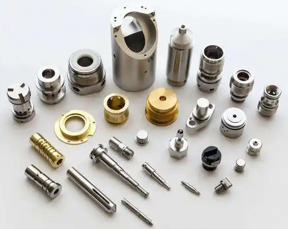
Applications and Industry Requirements
Precision machining serves critical roles across industries where component accuracy directly impacts system performance, safety, and reliability. Each industry sector presents unique requirements for material properties, dimensional tolerances, and surface finish specifications.
Aerospace Industry
Aerospace components demand exceptional reliability and weight optimization. Precision machining produces turbine blades, structural brackets, and engine components from advanced materials including titanium alloys, Inconel, and carbon fiber composites.
- Turbine blade profiles with ±0.0005" tolerances
- Landing gear components from high-strength steel
- Fuel system components requiring leak-proof sealing
- Structural brackets with complex geometries
Medical Device Manufacturing
Medical applications require biocompatible materials and exceptional surface finish quality. Surgical instruments, implants, and diagnostic equipment components must meet stringent regulatory standards and dimensional accuracy requirements.
- Orthopedic implants from titanium and cobalt chrome
- Surgical instruments with precise cutting edges
- MRI-compatible components from non-magnetic alloys
- Microfluidic devices for diagnostic applications
Automotive Sector
Automotive precision machining focuses on engine components, transmission parts, and safety-critical systems. High-volume production requires consistent quality and dimensional accuracy across thousands of parts.
- Engine blocks with precise cylinder bore dimensions
- Fuel injection components requiring tight tolerances
- Transmission gears with specific tooth profiles
- Brake system components for safety applications
Defense and Military Applications
Defense applications require components that perform reliably under extreme conditions. Precision machining produces weapon system components, guidance system parts, and communication equipment housings from specialized materials.
- ✔ Missile guidance components with micrometer tolerances
- ✔ Armor plating from hardened steel alloys
- ✔ Electronic enclosures for harsh environments
Electronics and Semiconductor
Electronic device manufacturing requires precise enclosures, heat sinks, and connector components. Miniaturization demands exceptional accuracy in microscale features and tight geometric tolerances.
- ✔ Heat sink fins with optimized thermal performance
- ✔ Connector housings with precise pin locations
- ✔ Optical component mounts for fiber optic systems
Material Considerations and Machinability
Material selection significantly influences precision machining parameters and achievable tolerances. Understanding material properties such as hardness, thermal conductivity, and work-hardening characteristics enables optimization of cutting parameters and tool selection for specific applications.
Aluminum Alloys
Excellent machinability with high material removal rates. Aluminum allows aggressive cutting parameters while maintaining dimensional accuracy and surface finish quality.
Key Characteristics:
- Low cutting forces required
- Excellent thermal conductivity
- Minimal work hardening tendency
- Superior surface finish achievable
Steel Alloys
Moderate machinability requiring careful parameter selection. Tool steel and stainless steel grades present challenges due to work hardening and abrasive wear characteristics.
Machining Considerations:
- Higher cutting forces required
- Heat generation management critical
- Tool wear acceleration with hardness
- Coolant application essential
Exotic Alloys
Titanium, Inconel, and other superalloys require specialized cutting tools and conservative parameters. These materials offer exceptional performance at elevated temperatures.
Special Requirements:
- Carbide or ceramic cutting tools
- Low cutting speeds essential
- Continuous coolant application
- Minimal work hardening zones
Engineered Plastics and Composites
High-performance polymers and fiber-reinforced composites present unique machining challenges including thermal sensitivity, delamination potential, and abrasive tool wear. Specialized cutting tools and parameters ensure quality results.
Thermoplastic Materials
PEEK, PEI, and PTFE require temperature control to prevent melting and surface degradation. Sharp cutting tools and adequate cooling maintain dimensional stability.
Composite Materials
Carbon fiber and fiberglass composites demand diamond-coated tools and specific cutting strategies to minimize delamination and achieve clean edge quality.
Quality Control and Measurement Systems
Precision machining quality control employs sophisticated measurement equipment and statistical process control methods to ensure consistent part quality and dimensional accuracy. Advanced measurement systems provide real-time feedback for process optimization and defect prevention.
Coordinate Measuring Machines (CMM)
CMM systems provide three-dimensional measurement capabilities with accuracies within 0.5 micrometers. Touch probe and optical scanning technologies enable rapid dimensional verification and geometric tolerance assessment.
- Bridge, cantilever, and gantry configurations
- Temperature-controlled measurement environments
- Automated measurement routines
- Statistical reporting and trend analysis
In-Process Measurement
On-machine measurement systems enable dimensional verification during machining operations. Touch probes and laser measurement systems provide immediate feedback for process correction and adaptive control.
- Tool wear compensation systems
- Workpiece setup verification
- Real-time dimensional monitoring
- Automated process adjustments
Quality Management Standards
Precision machining operations typically maintain ISO 9001:2015 certification with industry-specific standards such as AS9100 for aerospace and ISO 13485 for medical devices. These standards ensure consistent quality management practices and traceability requirements.
AS9100
Aerospace Quality
ISO 13485
Medical Devices
IATF 16949
Automotive Quality
Surface Measurement and Analysis
Surface texture measurement employs contact and non-contact methods to quantify roughness, waviness, and form parameters. Optical profilers and stylus instruments provide detailed surface characterization for quality verification and process optimization.
Contact Measurement
Stylus profilometers trace surface contours with diamond tips to measure Ra, Rz, and other roughness parameters with nanometer resolution.
Optical Methods
White light interferometry and confocal microscopy provide non-contact surface measurement with three-dimensional mapping capabilities.
Conclusion
Precision machining represents the convergence of advanced manufacturing technology, sophisticated equipment, and meticulous process control. Success in precision machining requires comprehensive understanding of material properties, cutting parameters, and quality control methods. Modern CNC machine tools combined with optimized cutting strategies enable manufacturers to achieve dimensional accuracies and surface finishes that meet the demanding requirements of aerospace, medical, automotive, and defense industries.
The continuous advancement of cutting tool materials, machine tool technology, and measurement systems expands the capabilities of precision machining operations. Organizations investing in precision machining capabilities position themselves to serve high-value markets where component quality directly impacts system performance and reliability.