Impeller machining stands as a pinnacle of precision manufacturing, transforming raw materials into intricate components that drive fluid systems in industries like aerospace, energy, marine, and pump manufacturing. Known for its ability to craft complex geometries with exacting tolerances, this process ensures impellers deliver optimal fluid efficiency, mechanical stability, and durability under demanding conditions. Whether shaping compressor wheels for jet engines or pump impellers for industrial fluid transfer, impeller machining combines advanced technologies, skilled craftsmanship, and rigorous quality control. In this comprehensive guide, we explore the defining characteristics, detailed processes, enabling technologies, and various machining types that make impeller machining a cornerstone of modern engineering.
Characteristics of Impeller Machining
Impeller machining is distinguished by its unique requirements, which stem from the component's critical role in fluid dynamics and mechanical performance. These characteristics shape every aspect of the custom impeller manufacturing process, from material selection to final inspection, demanding a blend of precision, adaptability, and innovation.
Complex Geometries
At the heart of CNC impeller design lies a symphony of complex geometries—twisted blades, thin-walled structures, and narrow, curved flow channels. These features are engineered to optimize fluid flow, whether accelerating air in a turbine or pumping water in an industrial system. For instance, a jet engine compressor impeller may feature blades with varying angles of twist and taper, designed to compress air efficiently at high speeds. Similarly, centrifugal pump impellers have flow channels with precise curvatures to minimize turbulence and cavitation. Achieving these shapes requires impeller machining techniques capable of navigating three-dimensional surfaces with sub-millimeter accuracy. Even a slight deviation—say, a 0.05mm error in blade thickness—can disrupt fluid dynamics, leading to efficiency losses or mechanical vibrations. This complexity often necessitates multi-axis CNC machines, which can maneuver tools in multiple directions to sculpt intricate profiles without compromising precision.
The challenge of complex geometries extends beyond machining to design and programming. Engineers use advanced CAD software to model impellers, incorporating computational fluid dynamics (CFD) to predict performance. These models guide the creation of toolpaths, which must account for potential tool interference in tight spaces, such as the narrow gaps between blades. For example, in a closed impeller with overlapping blades, toolpaths must be meticulously planned to avoid collisions while ensuring uniform material removal. This interplay of design and execution underscores why impeller machining is as much an art as a science.
Material Diversity
Impellers are crafted from a diverse array of materials, each chosen for specific performance criteria like strength, weight, corrosion resistance, or thermal stability. Common materials include lightweight aluminum alloys for high-speed applications, titanium alloys for their strength-to-weight ratio in aerospace, stainless steel for corrosion resistance in marine environments, and nickel-based superalloys for extreme temperatures in gas turbines. Each material presents unique machining considerations. Aluminum alloys, while relatively soft, are prone to chip adhesion, which can mar surface finishes. Titanium alloys, prized for their toughness, are notoriously difficult to machine due to their high hardness and low thermal conductivity, leading to rapid tool wear and heat buildup. Nickel-based superalloys, used in high-temperature applications, resist deformation but generate significant cutting forces, demanding robust tools and precise control.
Material selection also influences machining strategy. For instance, machining a titanium impeller for an aircraft engine requires low cutting speeds and high feed rates to minimize work hardening, where the material becomes tougher during cutting. Conversely, aluminum impellers CNC benefit from high-speed machining to achieve smooth finishes efficiently. Manufacturers must also consider material microstructure—forged titanium has fewer defects than cast versions, affecting tool life and surface quality. This diversity necessitates a deep understanding of material properties and their interaction with machining processes, ensuring that tools, parameters, and techniques are tailored to each impeller's requirements.
Precision and Dynamic Balance
Precision is non-negotiable in impeller CNC machining, where tolerances as tight as ±0.01mm are standard for critical dimensions like blade thickness, flow channel width, and hub diameter. Surface finishes must often reach Ra 0.8μm or smoother to reduce fluid friction and wear, particularly in high-performance applications like aerospace compressors. Such precision ensures that impellers operate efficiently, minimizing energy losses and maximizing throughput. For example, a poorly finished impeller in a centrifugal pump may increase turbulence, reducing flow rate and increasing power consumption.
Dynamic balance is equally critical, as impellers often rotate at speeds exceeding 10,000 RPM. Even a slight imbalance—measured in micrograms—can cause vibrations, leading to premature wear, noise, or catastrophic failure. Achieving balance requires not only precise machining but also rigorous testing. After CNC machining, impellers undergo dynamic balancing on specialized machines that detect and correct mass discrepancies, often by removing tiny amounts of material from specific areas. This process is iterative, as initial corrections may introduce new imbalances, requiring multiple rounds of adjustment. The interplay of dimensional precision and balance underscores the exacting nature of CNC impeller machining, where every micron matters.
The Impeller Machining Process
The journey from raw material to finished impeller is a multi-stage process that blends advanced technology with meticulous craftsmanship. Each step is designed to build on the previous one, progressively refining the component to meet stringent performance standards. This process is not linear but iterative, with constant feedback loops to ensure quality at every stage.
Design and Modeling
The process begins with design, where engineers use CAD software like CATIA, SolidWorks, or NX to create detailed 3D models of the impeller. These models capture every nuance of the component—blade curvature, hub geometry, flow channel profiles—and are validated using CFD simulations to predict fluid behavior. For instance, a turbine impeller might be optimized to maximize pressure rise while minimizing drag, requiring precise blade angles and channel shapes. The design phase also considers manufacturability, ensuring that complex features are feasible within machining constraints.
Once the design is finalized, CAM software (e.g., PowerMill, Mastercam) generates toolpaths for CNC machines. This step is critical, as toolpaths dictate how tools move across the workpiece, affecting accuracy, surface quality, and efficiency. For complex CNC impellers, toolpaths are often multi-layered, combining roughing passes to remove bulk material with finishing passes for precision. Advanced CAM algorithms optimize paths to minimize tool changes, reduce idle movements, and avoid collisions in tight areas like blade roots. Simulation tools verify these paths, visualizing the machining process to catch errors before cutting begins. This digital preparation lays the foundation for physical production, bridging the gap between concept and reality.
Rough and Finish Machining
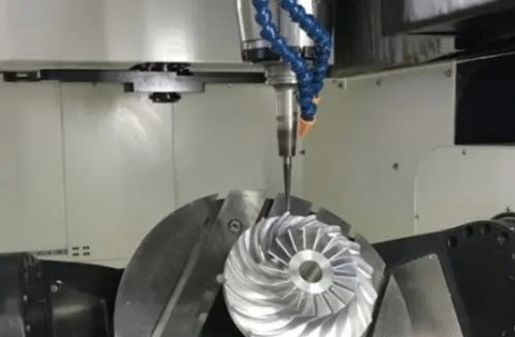
Rough machining is the first physical step, using three- or four-axis CNC machines to carve the impeller's basic shape from a raw blank—typically a forging, casting, or solid bar. Large-diameter tools, such as end mills or disc cutters, remove excess material rapidly, leaving a margin of 0.5-2mm for subsequent finishing. The goal is efficiency without compromising structural integrity, as excessive cutting forces can distort thin-walled sections. For example, roughing a titanium impeller might involve layered cuts, removing material in shallow passes to manage heat and stress.
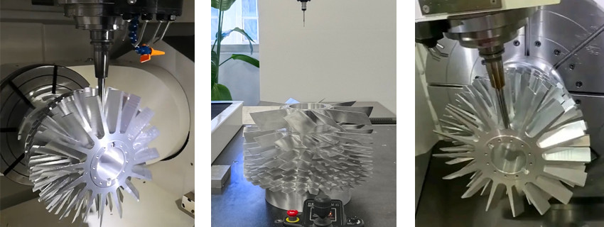
Finish machining refines the impeller's geometry, relying on five-axis CNC machines for their ability to access complex surfaces. Tools like ball-end mills, tapered cutters, or custom-profile knives sculpt blades and flow channels with micron-level precision. This stage demands careful control of cutting parameters—spindle speed, feed rate, and depth of cut—to achieve smooth finishes and tight tolerances. For instance, finishing a compressor impeller may use high-speed machining with small stepovers (e.g., 0.1mm) to create mirror-like surfaces, reducing aerodynamic drag. The process often involves multiple setups, repositioning the workpiece to machine different areas, each requiring precise alignment to avoid cumulative errors.
Both stages incorporate real-time monitoring, with sensors tracking cutting forces, tool wear, and vibration. Adaptive machining systems adjust parameters dynamically, slowing feeds if resistance increases or speeding up in lighter cuts, optimizing efficiency and tool life. This blend of brute force and finesse distinguishes impeller machining from simpler manufacturing tasks.
Surface Treatment and Inspection
After machining, impellers undergo surface treatments to enhance performance and durability. Polishing—manual, robotic, or chemical—achieves ultra-smooth finishes, critical for fluid efficiency and wear resistance. Sandblasting or shot peening may be used to improve fatigue strength, particularly for aerospace components. In high-demand applications, coatings like PVD (physical vapor deposition) or CVD (chemical vapor deposition) add layers of ceramic or metallic compounds, boosting resistance to corrosion, erosion, or heat. For example, a gas turbine impeller might receive a thermal barrier coating to withstand temperatures exceeding 1000°C.
Inspection is the final gatekeeper, ensuring the impeller meets design specifications. Coordinate measuring machines (CMM) scan surfaces to verify dimensions, checking features like blade thickness or channel width against tolerances. Laser scanners or white-light interferometry assess surface roughness, confirming finishes meet standards like Ra 0.4μm. Dynamic balancing tests, conducted on high-precision machines, measure mass distribution at operational speeds, correcting imbalances by removing material (e.g., drilling small holes) or adding weights. These tests are iterative, as corrections can shift balance elsewhere, requiring multiple cycles to achieve equilibrium.
Key Technologies in Impeller Machining
Impeller machining relies on a suite of advanced technologies, each addressing specific aspects of precision, efficiency, and reliability. These tools and techniques enable manufacturers to tackle the complexities of CNC impeller production, pushing the boundaries of what's possible in modern engineering.
Five-Axis Machining
Five-axis machining is the linchpin of impeller CNC production, offering unparalleled flexibility to shape intricate geometries. Unlike three-axis machines, which move tools in X, Y, and Z directions, five-axis systems add two rotational axes (e.g., A and C), allowing tools to tilt and pivot. This capability is essential for machining twisted blades or deep flow channels, where tools must approach from multiple angles to avoid interference. For example, machining a closed impeller with overlapping blades requires continuous tool reorientation to maintain contact with curved surfaces without colliding with adjacent features.
Tool posture optimization, driven by advanced control algorithms, ensures stability and accuracy. Inverse kinematics calculations adjust tool angles in real time, compensating for machine dynamics and workpiece geometry. High-precision spindles and linear motors enhance responsiveness, enabling smooth, vibration-free cuts. CNC Five-axis machining also supports simultaneous multi-surface machining, reducing setup times and improving consistency. However, it demands skilled programming and robust machine calibration, as even minor misalignments can amplify errors across complex toolpaths.
Tool Selection and Cutting Parameters
Choosing the right tools is critical, as impellers span a wide range of materials and geometries. Carbide tools, with their balance of hardness and toughness, are standard for stainless steel and titanium. Ceramic tools excel with high-temperature alloys, resisting wear at elevated cutting temperatures. Polycrystalline diamond (PCD) tools, though expensive, deliver superior performance with aluminum, producing mirror-like finishes with minimal adhesion. Tool geometry—flute count, helix angle, rake angle—is tailored to specific tasks. For instance, high-helix tools reduce cutting forces in thin-walled sections, while low-helix designs provide strength for roughing hard alloys.
Coatings like TiAlN, AlCrN, or diamond-like carbon (DLC) extend tool life by reducing friction and heat buildup. Cutting parameters—spindle speed, feed rate, depth of cut—are optimized to balance efficiency, tool longevity, and surface quality. High-speed machining (HSM) uses rapid spindle speeds (e.g., 20,000 RPM) and shallow cuts to minimize thermal distortion, ideal for finishing titanium impellers. Conversely, heavy roughing of steel may favor lower speeds with deeper cuts to maximize material removal. Cooling strategies, such as high-pressure coolant or cryogenic systems (e.g., liquid nitrogen), manage heat, especially in low-conductivity materials like titanium.
Parameter optimization often leverages machine learning, analyzing data from sensors to predict tool wear or surface defects. This data-driven approach allows manufacturers to fine-tune settings dynamically, adapting to variations in material properties or tool conditions.
Clamping, Simulation, and Verification
Clamping systems are engineered to secure impellers without inducing stress or deformation, particularly for thin-walled designs. Custom fixtures, such as vacuum chucks or flexible clamps, distribute forces evenly, while modular setups allow quick repositioning for multi-angle machining. Precision alignment, using laser trackers or touch probes, ensures workpieces are positioned within microns, minimizing cumulative errors across setups.
Simulation and verification tools are indispensable for error prevention. CNC simulation software (e.g., Vericut) models the entire machining process, visualizing toolpaths to detect collisions, overcuts, or gouging. Finite element analysis (FEA) predicts stresses and deformations, guiding fixture design and cutting sequences. For example, FEA might reveal that machining a thin blade from tip to root risks bending, prompting a reverse sequence to maintain rigidity. These tools create a virtual proving ground, allowing manufacturers to refine processes before cutting metal, saving time and materials.
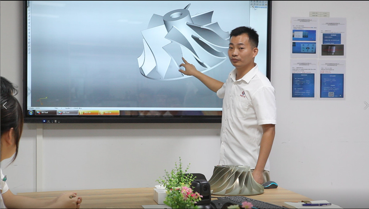
Kesu CNC Machining For Impellers
KeSu CNC manufacturing team, composed of professional engineers and machinists, applies optimized programming and efficient toolpaths for impeller company.
5-axis impeller continuous CNC machining provides greater accuracy and flexibility for producing complex impeller designs.
In CNC precision machining Kesu is among the top manufacturer of machine parts all over the world and in China they are the top 5 best service providers of CNC precision machining parts.
Machining Types for Impellers
Impeller machining employs a variety of techniques, each tailored to specific stages, materials, or geometric demands. These methods complement one another, enabling manufacturers to achieve the precision and efficiency required for high-performance impellers.
Milling
Milling is the dominant method for impeller machining, particularly for shaping complex surfaces like blades and flow channels. Five-axis CNC milling machines use tools such as ball-end mills, tapered end mills, or toroidal cutters to sculpt intricate profiles with high accuracy. The process excels at creating smooth transitions and precise curvatures, essential for fluid dynamics. For example, milling a centrifugal compressor impeller involves contouring blades with varying thicknesses, requiring small stepovers (e.g., 0.05mm) to achieve finishes of Ra 0.6μm.
High-speed milling, a subset of the technique, uses rapid spindle speeds and shallow cuts to reduce heat and vibration, ideal for finishing titanium or aluminum impellers. Trochoidal milling, with its circular toolpaths, minimizes tool load during roughing, extending life in hard alloys. Milling also supports adaptive strategies, adjusting feeds based on real-time cutting forces, ensuring consistency across large or complex workpieces. The versatility of milling makes it the backbone of impeller production, handling everything from rough shaping to final detailing.
Turning
Turning is employed for cylindrical or symmetrical features, such as impeller hubs, shafts, or outer diameters, typically during rough machining. CNC lathes rotate the workpiece against stationary tools, removing material efficiently to establish foundational geometries. For instance, turning a pump impeller hub ensures concentricity and dimensional accuracy before milling blades. The process is fast and cost-effective for bulk material removal, particularly with forgings or bar stock.
Advanced turning centers with live tooling can perform secondary operations, like drilling mounting holes, reducing the need for additional setups. Hard CNC turning, using CBN (cubic boron nitride) tools, finishes hardened steel or superalloy components to tolerances rivaling grinding. While turning is less common for complex blade machining, its role in preparing workpieces is critical, providing a stable base for subsequent operations.
Grinding and Polishing
Grinding and polishing refine impeller surfaces, achieving finishes that enhance fluid flow and durability. Precision grinding, using diamond or CBN wheels, corrects minor dimensional errors and smooths surfaces to Ra 0.4μm or better. For example, grinding a turbine impeller's blade tips ensures uniformity, reducing stress concentrations during rotation. Creep-feed grinding, with slow feeds and deep cuts, is used for hard alloys, balancing efficiency and precision.
Polishing—manual, robotic, or electrochemical—creates mirror-like finishes, critical for high-efficiency impellers. Robotic polishing systems, guided by 3D scans, ensure consistent results across complex surfaces, while electrochemical polishing removes micro-burrs without mechanical stress. These processes are vital for aerospace and energy applications, where surface imperfections can lead to cavitation or fatigue failure.
Electrical Discharge Machining (EDM)
Electrical Discharge Machining (EDM) is a specialized technique for hard or intricate features, particularly in materials like nickel-based superalloys. Wire EDM uses a thin wire to cut precise contours, ideal for small slots or blade root details. Sinker EDM employs a shaped electrode to erode material, suitable for deep, narrow channels inaccessible to milling tools. The process is non-contact, using electrical sparks to vaporize material, which eliminates cutting forces and tool wear.
EDM excels in finishing high-hardness components, achieving tolerances of ±0.005mm and finishes of Ra 0.2μm. For example, EDM might shape the intricate cooling channels in a gas turbine impeller, where traditional tools would struggle. However, EDM is slower than milling, making it a targeted solution for specific features rather than bulk machining. Hybrid approaches, combining EDM with milling, leverage the strengths of both for optimal results.
Conclusion
Impeller machining is a high-precision manufacturing process that combines advanced technologies, material expertise, and meticulous craftsmanship to produce complex components essential to fluid systems in aerospace, energy, marine, and industrial applications. Characterized by intricate geometries, diverse materials, and ultra-tight tolerances, it involves a multi-stage workflow—from CAD/CAM design and multi-axis CNC milling to grinding, polishing, and EDM. Each step ensures optimal aerodynamic performance, structural integrity, and dynamic balance. By leveraging key technologies like five-axis machining, adaptive toolpaths, and precision inspection systems, impeller CNC machining stands as a cornerstone of modern engineering, enabling high-efficiency, high-performance solutions in the world’s most demanding environments.
Frequently Asked Questions (FAQ)
Why is five-axis machining critical for impeller production?
Five-axis machining allows tools to approach the workpiece from multiple angles, which is essential for accurately shaping twisted blades and deep flow channels. It reduces the need for multiple setups and enables the machining of complex features without tool interference.
How do manufacturers ensure dynamic balance in impellers?
After CNC machining, impellers undergo dynamic balancing using specialized machines that detect and correct mass imbalances. This process involves removing or adding small amounts of material to ensure stable high-speed operation, minimizing vibration and wear.
What materials are commonly used for impellers and how do they affect machining?
Common materials include aluminum alloys, titanium alloys, stainless steel, and nickel-based superalloys. Each material has unique CNC machining characteristics—for example, titanium is heat-sensitive and wears tools quickly, while aluminum can lead to chip adhesion. Machining parameters must be tailored accordingly.
What quality control methods are used after machining?
Quality control includes dimensional inspection using coordinate measuring machines (CMM), surface roughness measurement with laser scanners or interferometers, and dynamic balance testing. Surface treatments like polishing or coating are also inspected to meet performance standards.
Which industries most commonly use impeller machining?
Impellers are widely used in industries such as aerospace (for example, in aircraft compressors), energy (including gas turbines and nuclear pumps), marine manufacturing (like propellers), and industrial pumps and compressors (such as centrifugal pumps and chemical pumps).