Computer Numerical Control (CNC) machining is a subtractive manufacturing process that uses computer-controlled tools to remove material from a workpiece, creating precise parts. It automates complex machining tasks, ensuring high accuracy and repeatability. CNC machining is integral to industries such as aerospace, automotive, medical, and electronics, producing components like engine parts, surgical implants, and circuit board enclosures.
This guide provides a detailed, technical overview of CNC machining, including its processes, components, programming, and applications. It is designed for professionals, engineers, and beginners seeking a systematic understanding of CNC technology.
Core Components of a CNC Machine
A CNC machine comprises several critical components that work together to execute precise machining tasks. Understanding these components is essential for operating and programming CNC systems effectively.
- Machine Bed: The foundation that supports all components, typically made of cast iron for stability. It absorbs vibrations during operation.
- Spindle: The rotating component that holds and drives the cutting tool or workpiece. Spindle speeds range from 1,000 to 20,000 RPM, depending on the machine type and material.
- Tool Holder: Secures the cutting tool to the spindle. Common types include collet chucks and hydraulic shrink-fit holders, with clamping forces up to 10,000 N for high-precision tasks.
- Control Unit (MCU): The computer that interprets G-code and controls machine movements. Modern MCUs feature touchscreens and support USB or Ethernet for program transfer.
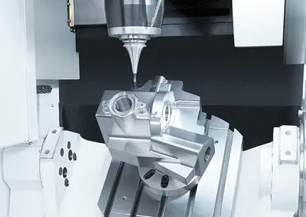
- Axis Drives: Motors (stepper or servo) that move the tool or workpiece along X, Y, and Z axes. Multi-axis machines (4- or 5-axis) enable complex geometries.
- Coolant System: Delivers coolant to reduce heat and remove chips. Flow rates typically range from 5 to 50 L/min, depending on the operation.
Each component must be calibrated and maintained to ensure precision. For example, spindle runout should not exceed 0.005 mm to avoid dimensional inaccuracies.
CNC Machining Processes
CNC machining encompasses various processes, each suited to specific applications. The most common processes are milling, turning, drilling, and grinding, detailed below with key parameters.
| Process | Description | Key Parameters | Applications |
|---|---|---|---|
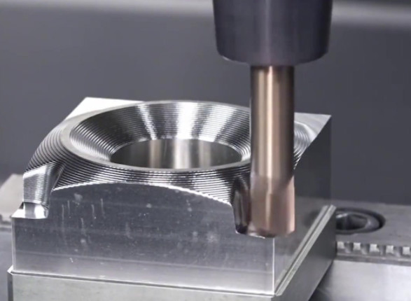
| Milling | Rotary cutters remove material from a stationary workpiece. | Feed rate: 50–500 mm/min; Spindle speed: 2,000–15,000 RPM; Depth of cut: 0.1–5 mm | Slots, pockets, complex surfaces (e.g., engine blocks) |
| Turning | A rotating workpiece is shaped by a stationary cutting tool. | Feed rate: 0.1–1 mm/rev; Spindle speed: 500–4,000 RPM; Depth of cut: 0.5–10 mm | Cylindrical parts (e.g., shafts, bolts) |
| Drilling | A rotating drill bit creates holes in the workpiece. | Feed rate: 0.05–0.5 mm/rev; Spindle speed: 1,000–10,000 RPM; Hole diameter: 0.5–50 mm | Holes for fasteners (e.g., brackets) |
| Grinding | An abrasive wheel removes material for a smooth finish. | Wheel speed: 1,500–3,000 m/min; Feed rate: 0.01–0.1 mm/pass; Surface roughness: Ra 0.1–0.8 µm | Precision surfaces (e.g., bearings) |
Each process requires specific tools and parameters, selected based on material properties and part geometry. For instance, milling aluminum requires higher spindle speeds than milling stainless steel due to aluminum’s lower hardness.
CNC Programming Fundamentals
CNC programming involves creating instructions that control machine movements and operations. The primary language is G-code, supplemented by M-code for auxiliary functions. Programming can be manual or automated using CAD/CAM software.
G-Code and M-Code
G-code controls motion, such as linear (G01) or rapid (G00) movements, while M-code manages machine functions, like spindle start (M03) or coolant on (M08). Common G-codes include:
- G00: Rapid positioning (e.g., G00 X10 Y20 moves to X=10, Y=20 at maximum speed).
- G01: Linear interpolation (e.g., G01 X10 Y20 F100 moves at a feed rate of 100 mm/min).
- G02/G03: Circular interpolation for clockwise (G02) or counterclockwise (G03) arcs.
M-codes are machine-specific but typically include:
- M03: Spindle on, clockwise (e.g., M03 S2000 sets 2,000 RPM).
- M05: Spindle stop.
- M08: Coolant on.
CAD/CAM Workflow
Modern CNC programming relies on CAD/CAM software. The workflow includes:
- Design: Create a 3D model using CAD software (e.g., SolidWorks, Fusion 360). Define dimensions and tolerances (e.g., ±0.01 mm for critical features).
- Toolpath Generation: Import the CAD model into CAM software (e.g., Mastercam) to define toolpaths, cutting tools, and parameters.
- Post-Processing: Convert toolpaths into machine-specific G-code using a post-processor.
- Simulation: Run a simulation to verify the program and avoid collisions.
Manual programming is used for simple parts but is prone to errors. CAM-generated programs are more reliable for complex geometries.

Materials and Tooling in CNC Machining
CNC machining processes a wide range of materials, each requiring specific tools and parameters. Material selection impacts machining time, tool life, and part quality.
Common Materials
Materials are chosen based on mechanical properties and application requirements. Common materials include:
- Aluminum: Lightweight, with a density of 2.7 g/cm³ and tensile strength of 90–700 MPa. Used for aerospace components.
- Stainless Steel: Corrosion-resistant, with a tensile strength of 500–2,000 MPa. Used for medical implants.
- Titanium: High strength-to-weight ratio (density: 4.5 g/cm³; tensile strength: 900–1,600 MPa). Used for aerospace fasteners.
- Plastics: Includes ABS, Nylon, and PEEK. Used for prototypes and low-stress components.
Tooling Selection
Cutting tools are selected based on material hardness and machining process. Common tool materials include:
- High-Speed Steel (HSS): Suitable for low-speed operations (e.g., 50–200 m/min cutting speed).
- Carbide: Harder and heat-resistant, used for high-speed machining (e.g., 200–1,000 m/min).
- Diamond-Coated Tools: Used for non-ferrous materials like aluminum to reduce wear.
Tool geometry, such as rake angle (5°–15° for metals) and flute count (2–6 flutes), affects chip removal and surface finish. Tool life is typically 30–120 minutes, depending on cutting conditions.
Applications of CNC Machining
CNC machining is versatile, serving diverse industries with high-precision requirements. Key applications include:
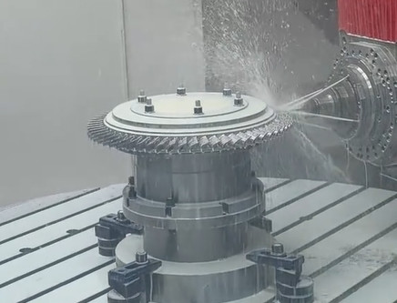
- Aerospace: Produces turbine blades, brackets, impellers, and structural components with tolerances as tight as ±0.005 mm.
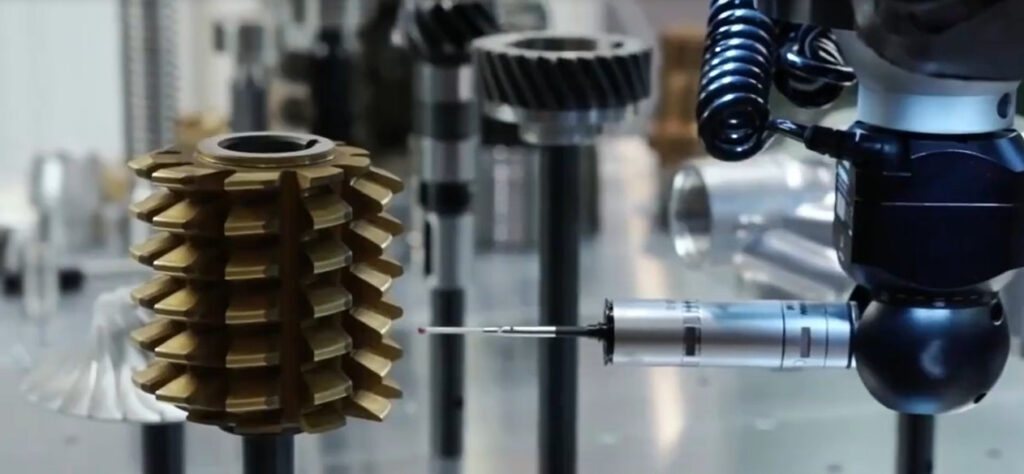
- Automotive: Manufactures engine blocks, transmission gears, and suspension components.
- Medical: Creates surgical tools, implants, and prosthetic components with biocompatible materials.
- Electronics: Fabricates enclosures, heat sinks, and connectors for circuit boards.
Each application demands specific tolerances and surface finishes. For example, aerospace parts require surface roughness of Ra 0.4–1.6 µm, while medical implants need Ra 0.1–0.4 µm for biocompatibility.
Setup and Operation Best Practices
Proper setup and operation are critical for achieving precision and efficiency in CNC machining. Key practices include:
- Workpiece Fixturing: Use vises, clamps, or vacuum tables to secure the workpiece. Ensure clamping force (e.g., 1,000–5,000 N) does not deform the part.
- Tool Calibration: Measure tool length and diameter with a presetter to ensure accuracy within ±0.01 mm.
- Program Verification: Run a dry cycle or simulation to confirm toolpaths and avoid crashes.
- Parameter Optimization: Adjust feed rates and spindle speeds based on material and tool data. For example, use a feed rate of 100–300 mm/min for aluminum milling.
- Maintenance: Regularly check spindle alignment, lubricate axes, and clean coolant filters to maintain performance.
Operators should monitor the first few cycles to detect issues like tool wear or vibration, which can affect tolerances.
Conclusion
CNC machining is a cornerstone of modern manufacturing, offering precision, repeatability, and versatility. By understanding its components, processes, programming, materials, and applications, professionals can optimize operations and produce high-quality parts. This guide provides a foundation for mastering CNC machining, emphasizing technical details and practical insights for reliable results.
Frequently Asked Questions (FAQ) About CNC Machining
What is CNC machining?
CNC (Computer Numerical Control) machining is a subtractive manufacturing process where computer-controlled tools remove material from a workpiece to create precise parts. It automates complex tasks, ensuring high accuracy and repeatability across industries like aerospace, automotive, and medical.
What are common CNC machining processes?
Process Key Parameters Applications
Milling Feed: 50–500 mm/min; Speed: 2,000–15,000 RPM Slots, engine blocks
Turning Feed: 0.1–1 mm/rev; Speed: 500–4,000 RPM Shafts, bolts
Drilling Feed: 0.05–0.5 mm/rev; Speed: 1,000–10,000 RPM Fastener holes
Grinding Wheel speed: 1,500–3,000 m/min; Ra 0.1–0.8 µm Bearings, precision surfaces
Why use coolant in CNC machining?
Coolant reduces heat, removes chips, and extends tool life. Typical flow rates: 5–50 L/min.
What are critical setup best practices?
Fixturing: Use vises/clamps (1,000–5,000 N force) to avoid workpiece deformation.
Tool Calibration: Measure tools within ±0.01 mm accuracy.
Parameter Optimization: Adjust feeds/speeds (e.g., 100–300 mm/min for aluminum).
Maintenance: Lubricate axes, clean coolant filters, and check spindle alignment.
How does multi-axis machining improve capabilities?
4- or 5-axis machines enable complex geometries (e.g., curved surfaces) without repositioning, reducing errors and setup time.