This guide provides a comprehensive overview of CNC machining for complex irregular parts, based on an engineering case study. It details the structural characteristics, machining strategies, and programming essentials for four-axis machining centers. The process is tailored for single-piece and small-batch production, offering practical insights for achieving high-quality results efficiently.
Introduction to Irregular Parts Machining
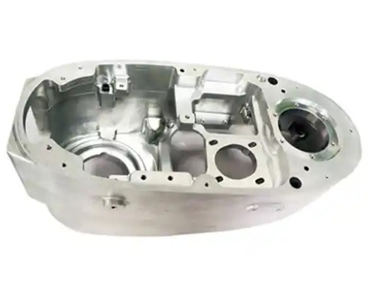
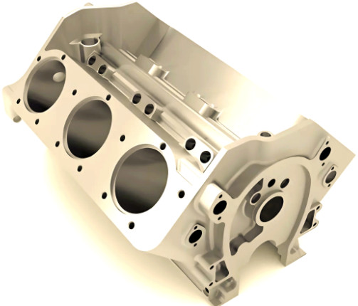
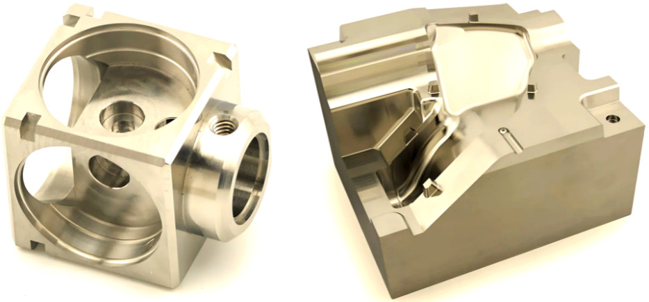
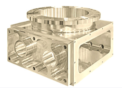
Irregular parts, characterized by complex geometries, pose significant challenges in manufacturing. For high-volume production, methods like casting, forging, or powder metallurgy are cost-effective but require substantial mold investments and long lead times. For low-volume production or product development phases, these methods are impractical due to cost and time constraints. Additive manufacturing, such as 3D printing, often fails to meet mechanical performance requirements. Consequently, subtractive CNC machining remains the most viable approach for producing complex irregular parts with high precision and reliability.
Traditional machining on conventional equipment involves multiple setups, extensive fixturing, and skilled operators, leading to prolonged development cycles and elevated costs. The advent of CNC technology, particularly four-axis machining centers, has revolutionized this process by enabling rapid, accurate, and flexible production of intricate parts.
Case Study: Irregular Connector Part
The case study focuses on a critical connector part used in a firing system, made from 2A12-T4 aluminum alloy. The part features complex geometry with high material removal rates, making it prone to deformation during machining. Key challenges include maintaining cylindricity between cylindrical surfaces and bosses, achieving specified surface roughness, and ensuring dimensional accuracy.
The machining process involves turning, milling, removing a process chuck, threading, and slotting. The part is machined from an aluminum rod, with initial turning to form a blank, followed by milling on a four-axis vertical machining center, threading on a CNC lathe, and final slotting.
Process Analysis and Machining Strategy
The machining strategy is designed to address the part’s complexity and material properties. The process begins with turning to create a blank, followed by milling to form the external geometry. A one-chuck-one-top clamping method is used on the four-axis machining center, with rough milling, semi-finish milling, and finish milling performed in sequence. The process chuck is then removed, and threading is completed on a CNC lathe using a double-top setup. Finally, slots are milled to complete the part.
The high material removal rate requires careful control to minimize deformation. The strategy emphasizes precise tool selection, optimized cutting parameters, and accurate programming to ensure dimensional accuracy and surface quality.
Turning the Blank
The initial turning operation forms the blank, as shown in the schematic diagram. The right end features a stepped cylindrical process chuck, while the inner bore is machined to final dimensions. Other surfaces retain a 0.5 mm machining allowance per side to accommodate subsequent milling operations. This step ensures the blank is dimensionally stable and prepared for complex milling on the four-axis machining center.

Milling Operations on Four-Axis Machining Center
Milling is the core of the machining process, performed on a four-axis vertical machining center. The following subsections detail the setup, tool selection, programming, and milling strategies.
Clamping and Workpiece Zero Point Setup
The workpiece is clamped on the fourth axis using a self-centering chuck at the right end and a tailstock with a center at the left end. A plug is used to support the left end. Dial indicators are employed to align the workpiece, ensuring runout is controlled within 0.1 mm. The tailstock is locked to secure the setup. The workpiece zero point is established based on the coordinate system, ensuring accurate tool paths.
Tool Selection and Cutting Parameters
Tool selection and cutting parameters are critical for achieving efficiency and quality. The following principles guide the process:
- Rough milling uses large-diameter tools to maximize material removal.
- Finish milling employs end mills for precision.
- A φ6 mm carbide tool is used for milling long R3.5 mm slots.
- Tool diameter is selected based on part dimensions, material removal rate, and cost.
- Rough milling parameters prioritize shallow depth of cut, large width of cut, and high feed rate.
- Finish milling parameters focus on low feed rate and large depth of cut for surface quality.
- Tool length is minimized to enhance rigidity and stability.
The table below summarizes the tool specifications and cutting parameters:
| Operation | Tool Type | Diameter (mm) | Feed Rate (mm/min) | Spindle Speed (r/min) | Depth of Cut (mm) |
|---|---|---|---|---|---|
| Rough Milling | End Mill | 12 | 1500 | 3000 | 0.5 |
| Semi-Finish Milling | End Mill | 8 | 1000 | 3000 | 0.25 |
| Finish Milling | End Mill | 8 | 800 | 3000 | 0.1 |
| Slot Milling | Carbide End Mill | 6 | 1000 | 3000 | 0.2 |
Programming with UG8.0
Programming is performed using UG8.0, with the following preparation steps:
- Create four parent nodes: program, tool, geometry, and method.
- Define operations, including 3-axis 2-linkage planar milling, cavity milling, fixed-axis contour milling, and 3- to 5-axis variable-axis contour milling.
- Create the digital model, adjusting dimensions to account for tolerances and simplifying interrupted surfaces for cleaner tool paths.
Rough Milling
Rough milling removes the bulk of the material in three stages:
- Workpiece Geometry Zero Point: Safety distances are set to prevent tool collisions, and the machine coordinate system is accurately defined.
- Cavity Milling (Upper and Lower Parts): The cavity milling function is used with a manual cutting depth set to half the blank’s maximum diameter.
- Side Milling: Planar milling is applied to remove remaining material, with specified cutting areas, blank distances, and bottom allowances.
Semi-Finish Milling
Semi-finish milling refines the part’s geometry, leaving a 0.25 mm allowance. Key operations include:
- Upper and Lower Parts: The remaining milling function is used with a φ8 mm end mill, feed rate of 1000 mm/min, and spindle speed of 3000 r/min.
- Slots: Planar milling is applied with a 5° diagonal approach to minimize tool wear.
Finish Milling
Finish milling achieves final dimensions and surface quality. Key operations include:
- Step Side Surfaces: Variable-axis contour milling is used with a φ8 mm end mill, streamline drive method, and projection vector toward the drive body.
- Arc Surfaces: Multi-axis milling is applied with a cylindrical surface drive, constant stepover, and knife-axis projection to ensure high cylindricity.
- Planar Surfaces: Face milling is used with a reciprocating tool path and vertical knife-axis orientation.
- R2 mm Surface: Fixed-axis contour milling is applied with a 0.1 mm maximum stepover for surface roughness.
- Toleranced Surfaces: Separate programs with tool compensation allow operators to adjust dimensions iteratively.
Removing the Process Chuck
The process chuck is removed using contour milling with a hybrid milling strategy. The chuck is modeled as a square for programming simplicity. Cutting parameters include a spindle speed of 3000 r/min, feed rate of 1500 mm/min, and depth of cut of 0.25 mm per layer, minimizing deformation.
Threading
Threading is performed on a CNC lathe using a double-top setup with a custom plug. This ensures concentricity and dimensional accuracy of the threads.
Slot Milling
Slots on the arc surface are milled by projecting the slot contour onto a plane and using planar milling. Light cuts and high feed rates prevent deformation, ensuring slot accuracy.
Conclusion
Compared to traditional machining, which requires extensive fixturing and weeks of preparation, the CNC process described completes the part in approximately 14 hours. The part meets all dimensional and surface quality requirements, demonstrating the efficiency and precision of four-axis CNC machining for complex irregular parts. This approach is highly practical for single-piece and small-batch production, offering a reliable solution for manufacturers.