Introduction to Cold Stamping and Mold Importance
Cold stamping is a widely adopted manufacturing process in industries such as automotive, electronics, aerospace, and consumer goods due to its ability to produce high-quality, lightweight, and cost-effective components. Steel sheets and strips, which account for approximately 67% of raw materials in cold stamping, are transformed into precise parts through molds. The mold's accuracy, particularly in key components like blade edges, profiles, clearances, and positioning systems, directly impacts the quality and stability of stamped products. Among these, the positioning pin holes in Cr12MoV molds are critical for ensuring precise alignment during static and dynamic validation, as well as in actual stamping operations. This article examines the processing techniques for Cr12MoV mold positioning pin holes, focusing on methods to achieve reliable positioning and uniform clearance.
Significance of Accurate Pin Hole Processing
Accurate positioning pin holes are essential for maintaining mold stability and ensuring consistent part quality in cold stamping. The mold's key components, including punch, die, and insert blocks, rely on pin holes for precise alignment. Incorrectly processed pin holes can lead to misalignment, causing uneven clearances, burrs on stamped parts, and reduced mold durability. For materials like Cr12MoV, which undergo vacuum heat treatment to achieve 56–60 HRC, the challenge lies in managing dimensional changes and hole shrinkage caused by heat treatment. Traditional processing methods often result in hole misalignment or deformation, necessitating rework that increases time and cost. The following sections detail the limitations of conventional approaches and introduce optimized methods to address these issues.
Limitations of Conventional Pin Hole Processing
Conventional pin hole processing for Cr12MoV molds involves drilling pre-holes with a 0.2 mm allowance before heat treatment, assembling the mold with the template, and performing match-drilling and reaming. After numerical control (NC) machining and polishing, the mold undergoes vacuum heat treatment. However, this approach has significant drawbacks:
- Hole Misalignment Post-Heat Treatment: Cr12MoV molds experience slight deformation and hole shrinkage during vacuum heat treatment, causing the pin holes to misalign with the template holes during final assembly. This leads to uneven clearances and burrs on stamped parts.
- Complex Rework Processes: To correct misaligned holes, manufacturers often resort to time-consuming methods such as enlarging holes via wire electrical discharge machining (EDM) or filling holes with plugs, followed by welding, grinding, and re-drilling. These processes are labor-intensive and inefficient.
- Reduced Mold Reliability: Misaligned pin holes compromise the mold's ability to maintain stable positioning during dynamic validation and stamping, leading to inconsistent part quality and increased maintenance costs.
These limitations highlight the need for improved pin hole processing techniques that account for material behavior during heat treatment and ensure precise alignment.
Optimized Processing Methods for Cr12MoV Pin Holes
To address the challenges of conventional methods, four optimized processing techniques have been developed for Cr12MoV mold positioning pin holes. These methods account for material deformation, ensure precise alignment, and enhance mold reliability. Each method is tailored to specific mold structures and processing requirements, as described below.
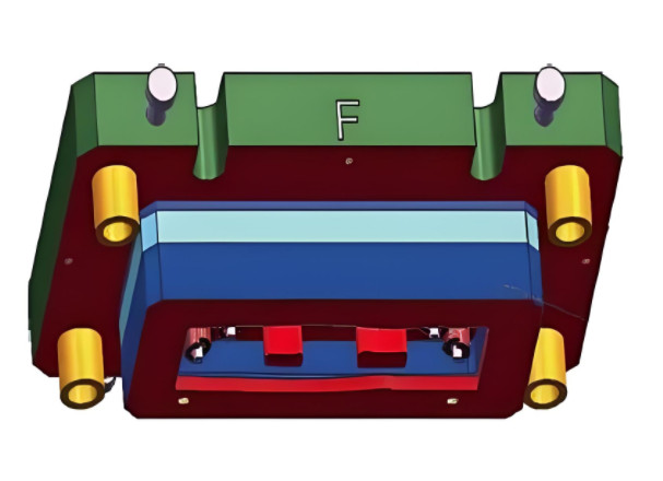
Method 1: Staged Pin Hole Processing for Non-Recessed Modules
For modules without recesses or retaining walls, the pin holes are processed in stages to accommodate heat treatment effects. The process begins by match-drilling and reaming pin holes in the module and mold base to a size one specification smaller than the design (e.g., ≤4 mm). During the initial NC machining of profiles and blade edges, the module's pin holes are enlarged to the design specification before vacuum heat treatment. After heat treatment, the mold base's pin holes are match-drilled and reamed with the module to achieve the final size. This method may involve using stepped positioning pins or manually marking module outlines as a reference for alignment during assembly.
Key Parameters:
| Stage | Pin Hole Size | Processing Step |
|---|---|---|
| Initial | ≤4 mm | Match-drill and ream module and mold base |
| Pre-Heat Treatment | Design specification | Enlarge module pin holes |
| Post-Heat Treatment | Design specification | Final match-drill and ream with mold base |
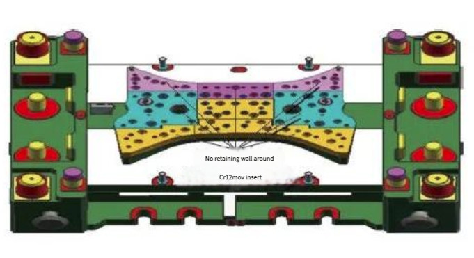
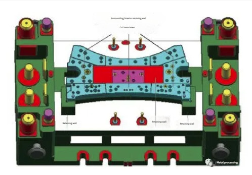
Method 2: Pre-Heat Treatment Pin Hole Drilling for Recessed Modules
For modules with retaining walls or recesses, which restrict movement in X, Y, and Z directions due to bolts and structural constraints, pin holes are drilled and reamed only in the module before heat treatment. The mold base's pin holes are not processed at this stage. After initial NC machining, the module undergoes vacuum heat treatment, and the mold base's pin holes are match-drilled and reamed with the module before final NC machining. This method ensures uniform machining allowances and precise positioning, as the module's movement is restricted by its structural design.
Key Parameters:
- Module pin hole drilling: Performed to design specification before heat treatment.
- Mold base pin hole processing: Conducted post-heat treatment during final assembly.
- Machining allowance: 0.6–0.8 mm per side for profiles and blade edges before heat treatment.
Method 3: Blind Pin Hole Processing with Soft Plugs
For side or upper modules with blind pin holes, the mold base and module are initially match-drilled and reamed to a size one specification smaller than the design (e.g., ≤4 mm). Before heat treatment, the module's pin holes are enlarged to a size one specification larger (e.g., ≥6 mm). After heat treatment, soft plugs made of 45 steel with vent flats are inserted into the enlarged holes. Before final NC machining, the mold base's pin holes serve as a reference for match-drilling and reaming the module's pin holes to the design specification. Cylindrical pins with vent flats (e.g., GB120-86 B-type) are used for final assembly.
Key Parameters:
| Stage | Pin Hole Size | Processing Step |
|---|---|---|
| Initial | ≤4 mm | Match-drill and ream module and mold base |
| Pre-Heat Treatment | ≥6 mm | Enlarge module pin holes |
| Post-Heat Treatment | Design specification | Insert soft plugs, match-drill, and ream |
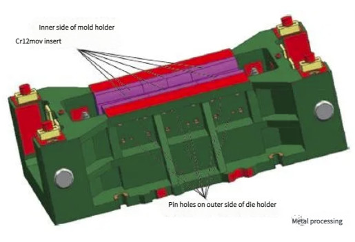
Method 4: Through-Hole Processing for Upper Modules
For upper modules, blind pin holes can be converted to through-holes to simplify processing. Through-holes are drilled and reamed or processed using slow wire EDM to achieve precise tolerances. To prevent pin loosening during stamping, through-holes can be fitted with threaded plugs or elastic split sleeves. To address verticality issues caused by heat treatment deformation, cylindrical pins are used for trial fitting, and any problematic holes are reamed before final match-drilling and reaming with the mold base.
Key Parameters:
- Through-hole processing: Slow wire EDM or drilling/reaming to achieve ±0.01 mm tolerance.
- Pin retention: Threaded plugs or elastic split sleeves to prevent loosening.
- Verticality correction: Reaming problematic holes before final match-drilling.
Implementation and Validation
These optimized methods have been implemented and validated in Cr12MoV mold manufacturing and maintenance. By accounting for heat treatment deformation and tailoring processing to specific mold structures, these techniques ensure precise pin hole alignment and stable mold performance. Collaboration with heat treatment providers to control vacuum quenching quality further enhances outcomes. The methods have proven effective in reducing rework, improving part quality, and extending mold life, making them suitable for widespread adoption in cold stamping mold production.
Conclusion
Precise positioning pin hole processing is critical for Cr12MoV molds in cold stamping, directly affecting part quality and mold reliability. Conventional methods often fail to account for heat treatment deformation, leading to misalignment and rework. The four optimized methods presented—staged processing for non-recessed modules, pre-heat treatment drilling for recessed modules, blind hole processing with soft plugs, and through-hole processing for upper modules—address these issues systematically. By incorporating specific machining allowances, staged processing, and structural considerations, these techniques ensure accurate alignment, uniform clearances, and stable performance, offering practical solutions for mold manufacturers.