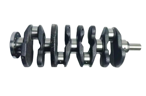
The crankshaft is a critical component of diesel engines, often referred to as the heart of marine diesel engines due to its essential role in power transmission. Its service life must match that of the vessel, typically exceeding 20–30 years. The crankshaft accounts for approximately one-third of the engine’s total cost, underscoring its economic significance. The oil passages within the crankshaft, which facilitate lubrication and cooling, demand high precision and surface quality. These passages, particularly the intersecting oblique oil holes, present significant machining challenges due to their complex geometry and the material’s poor machinability. This article provides a comprehensive analysis of the machining difficulties associated with deep hole drilling of crankshaft oil passages and outlines a systematic approach to overcoming these issues through process optimization and advanced machining techniques.
Challenges in Deep Hole Drilling of Crankshaft Oil Passages
Deep hole drilling of crankshaft oil passages, particularly intersecting oblique holes, poses several technical difficulties. These challenges stem from the spatial complexity of the holes, the material properties, and the limitations of conventional machining methods.
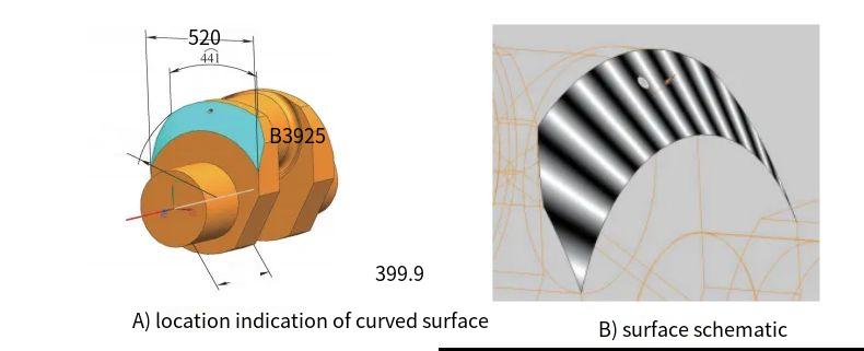
Difficulty in Positioning on Curved Surfaces
Oblique oil holes are typically located on the curved surfaces of the crankshaft, such as the main journal or crankpin. The curvature causes uneven cutting forces on the drill’s cutting edges, leading to potential deflection or deviation from the intended path. In severe cases, this can result in drill breakage. For instance, when drilling a hole on a cylindrical surface, the drill’s cutting edges experience asymmetric forces, causing the tool to shift upward or downward, which compromises positional accuracy and increases the risk of tool failure.
Challenges with Intersecting Oblique Holes
The oil passages in a crankshaft often involve two deep holes intersecting at an angle, creating a complex geometry. After the first hole is drilled, machining the second hole becomes challenging due to the reduced rigidity and strength of the slender deep-hole drilling tool. At the intersection point, the tool encounters abrupt changes in cutting conditions, leading to vibration, deviation, or tool breakage. Additionally, the intersection reduces internal cooling pressure, which can cause the tool to seize or break, increasing machining risks and complexity.
Poor Chip Evacuation and Tool Wear
Deep hole drilling generates long, continuous chips that are difficult to evacuate due to the extended chip evacuation path. This leads to chip accumulation, which can damage the machined surface, leaving tool marks or vibration patterns that degrade surface quality. The limited chip evacuation also restricts heat dissipation, causing elevated cutting temperatures that accelerate tool wear and reduce tool life. Under cutting forces, the slender tool shank may deflect, causing the hole’s axis to deviate from the theoretical centerline, further compromising dimensional accuracy.
Process Design and CNC Machining Strategy
The crankshaft converts the reciprocating motion of the connecting rod into rotational motion to output power, making it a vital engine component. The oblique oil holes serve as conduits for lubricating oil, ensuring smooth operation of the main and connecting rod journals. The spatial orientation of these holes complicates both design and machining. Below is a detailed breakdown of the machining process and the CNC strategy employed to address the challenges.
Technical Requirements for Oil Passage Machining
The crankshaft’s oil passages must meet stringent dimensional, positional, geometric, and surface quality requirements to ensure engine performance. For example, a typical oblique oil hole has the following specifications:
- Angle relative to the horizontal plane: 31° ± 15′
- Vertical distance from the main journal: 360.5 ± 0.5 mm
- Horizontal distance from the main journal: 581 ± 0.4 mm
- Hole diameter: φ20H10 (+0.084 mm, +0 mm)
- Hole depth: 698 mm
- Surface roughness: Ra 6.3 μm
- Parallelism of adjacent hole axes: ≤0.15 mm
- Straightness: ≤0.08 mm
- Radial runout: ≤0.1 mm
These requirements necessitate precise control over machining parameters and tool selection to achieve the desired accuracy and surface quality.
Selection of Machining Method
Several deep hole drilling methods were evaluated, including flat drills and BTA drilling. Flat drills are suitable for holes with a length-to-diameter ratio (L/D) less than 10, which is insufficient for the deep holes in crankshafts. BTA drilling, while effective, requires specialized equipment, incurs high costs, and is less suitable for large crankshafts. Gun drilling was selected due to its ability to achieve high precision (IT7–IT10), surface roughness (Ra 3.2–12.5 μm), and roundness error (5–10 μm). Gun drilling also offers cost efficiency, shorter manufacturing cycles, and high machining accuracy, making it ideal for crankshaft oil passage machining.
Positioning Reliability
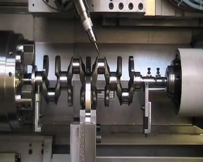
Reliable positioning is critical for accurate machining. The process utilizes a CNC turn-milling center (e.g., HTM1251000 with Siemens 840D system) equipped with two rotary heads, three linear axes (X, Y, Z), and two rotary axes (B, C). The crankshaft is positioned using a front fixed center and a rear floating center. The front center restricts movement in the X, Y, and Z axes, while the rear center restricts Y and Z axis movements. This setup limits five degrees of freedom, leaving only rotation around the X-axis unrestricted, ensuring reliable positioning based on the six-point positioning principle.
CNC Programming and Simulation
A three-dimensional model of the crankshaft is created using CAD software to determine the spatial coordinates of the oil hole centers relative to the crankshaft’s reference points. The milling head is rotated to align with the hole’s orientation, and a CNC program is developed for drilling. Simulation software is used to model the machining process, including the machine structure, fixtures, tools, and control system. This simulation optimizes the CNC program, minimizes machining time, extends tool life, and prevents issues such as overcutting, undercutting, or machine collisions.

Optimized Machining Process
The deep hole drilling process for crankshaft oil passages was optimized to address the identified challenges. The process involves several key steps, each designed to enhance precision, tool life, and surface quality.
Step 1: Milling a Normal Plane and Drilling a Pilot Hole
The process begins by milling a flat plane normal to the hole’s axis on the curved surface of the crankshaft. A φ20 mm end mill is used to create a φ30 mm cavity, providing a stable platform for the pilot hole. The pilot hole, drilled with a φ20 mm gun drill, ensures accurate guidance and support for subsequent deep hole drilling. This step mitigates the positioning difficulties associated with curved surfaces and reduces the risk of drill deviation.
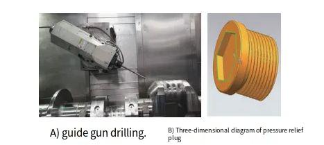
Step 2: Addressing Intersection Challenges
When drilling the second intersecting hole, a pressure-relief plug is used to seal the first hole at the intersection point. This plug, inserted after drilling a 15 mm deep hole at the intersection, maintains internal cooling pressure and stabilizes the tool. To further reduce tool stress, the spindle speed and feed rate are reduced to one-third of their original values during intersection machining, minimizing vibration and tool breakage risks.
Step 3: Optimizing Cutting Parameters and Cooling
Effective chip evacuation and heat dissipation are critical for deep hole drilling. The optimized cutting parameters for a φ20 mm gun drill are a spindle speed of 410 rpm and a feed rate of 56 mm/min. These parameters ensure stable chip formation and evacuation, with no chip adhesion observed. To prevent tool damage from sudden feed rate changes, the tool is retracted by 1 mm before increasing the spindle speed and feed rate, and internal cooling pressure is maintained for 10 seconds to stabilize the process. This approach eliminates abrupt cutting force changes, reducing the risk of tool chipping or breakage.
Step 4: Controlled Tool Retraction
Due to the tool’s deflection during deep hole drilling, rapid retraction is avoided to prevent surface damage. A retraction feed rate of 180 mm/min was found to be optimal, balancing efficiency and surface quality while minimizing tool stress.
Cutting Parameters and Machining Time
The following table summarizes the optimized cutting parameters and machining times for the crankshaft’s oblique oil passages.
| Parameter | Value |
|---|---|
| Hole Diameter | φ20 mm |
| Hole Depth | 698 mm |
| Spindle Speed | 410 rpm |
| Feed Rate | 56 mm/min |
| Retraction Feed Rate | 180 mm/min |
| Surface Roughness | Ra 6.3 μm |
| Machining Time per Hole | Approx. 25 min |
Conclusion
Through systematic analysis of deep hole drilling mechanisms and optimization of cutting parameters, the machining of crankshaft oblique oil passages was successfully achieved. By leveraging advanced CNC turn-milling centers, gun drilling, and precise process control, the challenges of positioning, tool wear, chip evacuation, and intersection machining were effectively addressed. This approach provides a reliable and efficient solution for producing high-precision crankshaft oil passages, meeting the stringent requirements of diesel engine manufacturing.