Thin-walled mold parts are common in precision machining but pose significant challenges due to their low rigidity and susceptibility to deformation during clamping. This article presents a detailed design of a specialized fixture for machining a thin-walled mold part, specifically a locking insert used in stamping molds. The fixture employs lateral locking with screws and rods to achieve rapid machining while resolving issues of elastic deformation and concentricity, thereby enhancing production efficiency and part quality.
Overview of Thin-Walled Mold Parts
Thin-walled parts, characterized by a small thickness in the radial direction, are prevalent in industries requiring high-precision components, such as mold manufacturing. These parts are difficult to clamp and machine due to their poor surface rigidity and low strength. During CNC lathe machining, clamping often induces elastic and plastic deformation, leading to irregular dimensional changes after unclamping. This results in increased geometric errors, compromised dimensional accuracy, and a higher risk of scrap parts, which elevate material and processing costs.
The objective of this study is to address clamping and machining difficulties for a specific thin-walled mold part through the design of a specialized fixture. The fixture enables rapid turning while minimizing deformation, ensuring dimensional precision, and improving production efficiency.
Part Description and Specifications
The part under consideration is a locking insert for a stamping mold, made from ASSAB88 cold-work mold steel (a high-quality Swedish steel). After heat treatment, it requires precision CNC lathe machining to meet stringent dimensional tolerances. The part’s key features are as follows:
| Feature | Specification |
|---|---|
| Outer Diameter | φ108 ± 0.01 mm |
| Through-Hole Diameter | φ88 ± 0.1 mm |
| Counterbore Diameter | φ97.5 ± 0.01 mm, depth 10 mm |
| Straight Grooves | Width 35 ± 0.05 mm, depth 17.5 mm, bottom fillet R3.0 mm, symmetrically on both sides |
| Arc Grooves | 4 grooves at 90° intervals, R9.5 mm, depth 10 mm on outer end face |
The presence of symmetrical 35 mm wide straight grooves significantly reduces the part’s rigidity and strength, making clamping particularly challenging. Even minimal clamping force can cause elastic deformation, complicating the achievement of required tolerances.
Clamping Challenges with Conventional Methods
Two conventional clamping methods—self-centering hard jaws and soft jaws—were analyzed to understand their limitations for this thin-walled part.
Self-Centering Hard Jaw Clamping
In hard jaw clamping, three small arc points on the jaw tips grip the part’s outer diameter. The concentrated clamping force at these points causes significant deformation. After clamping, the outer diameter and inner hole exhibit macroscopic deformation. Although the machined surfaces may have good roundness during machining, unclamping allows the part to spring back, resulting in an irregular contour. Excessive clamping force increases deformation, while insufficient force risks part slippage or ejection during machining, posing safety hazards.
Self-Centering Soft Jaw Clamping
Soft jaws, made from unhardened material, are shaped to match the part’s outer diameter, providing more stable and uniform clamping. However, clamping near the straight grooves, where wall thickness is minimal, still induces significant elastic deformation. Excessive force may even cause cracking near the grooves, leading to part failure or ejection. This method also presents significant machining difficulties and safety risks.
Both conventional methods fail to adequately address the part’s low rigidity, resulting in deformation, poor dimensional accuracy, and safety concerns.
Design of the Specialized Fixture
Based on the limitations of conventional clamping methods, a specialized fixture was designed to enable rapid and precise machining of the thin-walled part. The fixture uses lateral locking with screws and rods to eliminate radial clamping forces, thereby minimizing elastic deformation.
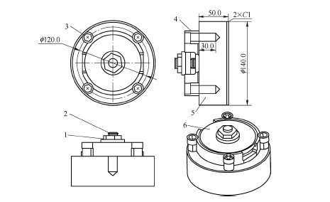
Fixture Structure
The fixture consists of a circular disk (diameter 140 mm, thickness 50 mm) with the following features:
- Four M12 × 1.75 mm threaded holes, evenly spaced at 90° on a φ120 mm end face.
- A central M16 threaded hole, 30 mm deep.
- A 5 mm wide, 5 mm deep annular groove at φ88 mm on the end face, serving as a clearance for boring the φ88 mm through-hole.
- 1 mm × 45° chamfers on both outer edges of the end faces.
Additional components include:
- Four M12 × 1.75 mm screws for locking the part in the R9.5 mm arc grooves.
- Four equal-height open washers to support the screws, ensuring uniform locking force.
- An M16 screw and nut with a circular washer for securing the part during outer diameter machining.
Fixture Functionality
The fixture operates in two stages: inner hole machining and outer diameter machining, all within a single clamping setup.
Inner Hole Machining: The part is placed against the fixture’s flat surface, with four M12 screws locking into the R9.5 mm arc grooves. Equal-height open washers are inserted beneath the screws to stabilize the locking force, preventing part movement during machining. The annular groove allows the boring tool to fully machine the φ88 mm through-hole without interference. A lever dial indicator ensures the inner contour’s coaxiality before machining all inner features.
Outer Diameter Machining: Without removing the M12 screws, a circular washer is placed on the 10 mm deep counterbore step. An M16 screw, inserted through the central threaded hole, and a nut secure the washer, locking the part. The M12 screws are then removed, and the outer diameter is machined. The 1 mm × 45° chamfer on the fixture provides clearance, with a machining allowance of 0.1–0.4 mm.
This design eliminates radial clamping, relying entirely on lateral locking to secure the part. The fixture’s high rigidity and stable locking ensure minimal vibration during machining, improving dimensional accuracy and surface finish.
Machining Process and Inspection Results
The machining process using the specialized fixture is systematic and precise, ensuring high accuracy and efficiency.
Machining Process
- Clamp the circular disk fixture onto the CNC lathe chuck. Use a lever dial indicator to calibrate the fixture’s flatness within 0.002 mm.
- Place the part against the fixture’s flat surface and install four M12 screws into the R9.5 mm arc grooves.
- Insert four equal-height open washers beneath the M12 screws and lightly tighten the screws.
- Calibrate the part’s inner contour coaxiality using a lever dial indicator, then fully tighten the M12 screws and machine all inner hole features.
- After inner hole machining, place the circular washer on the 10 mm deep counterbore step without removing the M12 screws.
- Install the M16 screw through the central threaded hole, secure it with a nut to lock the circular washer, and remove the M12 screws.
- Machine the outer diameter contour.
Inspection Results
A sample part was inspected using a precision coordinate measuring machine (CMM). The results are summarized below:
| Feature | Specified Dimension | Actual Dimension | Roundness Contour |
|---|---|---|---|
| Counterbore Diameter | φ97.5 ± 0.01 mm | φ97.506 mm | 0.0054 mm |
| Outer Diameter | φ108.0 ± 0.01 mm | φ107.9905 mm | 0.0051 mm |
| Concentricity (Inner Hole to Outer Diameter) | - | 0.0016 mm | - |
The results confirm that the part exhibits no deformation, with all dimensions and roundness contours within tolerances. The single-clamping process ensures excellent concentricity, eliminating the need for secondary clamping and reducing setup time.
Conclusion
The specialized fixture effectively addresses the clamping and machining challenges of thin-walled mold parts. By using lateral locking with screws and rods, it eliminates radial clamping forces, preventing elastic deformation. The single-clamping process enables rapid machining of both inner and outer features, ensuring high concentricity, dimensional accuracy, and surface quality. Inspection data validate the fixture’s reliability, demonstrating its suitability for high-precision, high-efficiency production. This design offers a practical and robust solution for machining thin-walled parts, significantly improving manufacturing outcomes.