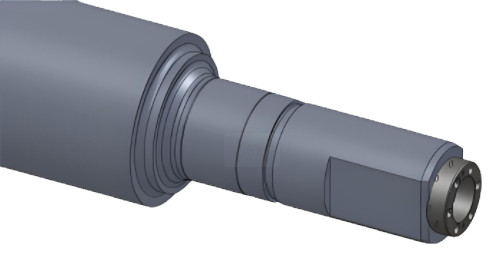
The roller end bushing is a critical component in the main drive system of a steel mill’s hot rolling process, connecting the universal joint shaft to the work roll. In a 2,032 mm hot rolling mill, issues such as excessive wear on the roller end bushing and work roll flat head led to drive shaft instability, equipment deterioration, and frequent maintenance. This article details the optimization of the roller end bushing design, focusing on structural enhancements and the application of laser cladding with wear-resistant materials to improve service life and reduce maintenance costs.
Background and Problem Analysis
In the hot rolling mill, the main drive shaft, supported by the motor and work roll at its ends and balanced by a hydraulic cylinder, exhibited significant vibration due to wear in the roller end bushing and work roll flat head. The bushing and flat head operate with clearance fit and no lubrication, leading to relative motion and wear during operation. This wear caused drive shaft instability, reduced universal joint life, bolt fractures, and cracks in the bushing’s fillet, resulting in equipment downtime. The bushing and flat head had short service lives, requiring frequent repairs and increasing maintenance costs. Improper handling risked major equipment damage.
Monitoring data revealed that the bushing’s inner bore exhibited tapered wear, with greater wear at the outer end than the inner end. On-site inspections and comparisons with other bushings identified the root cause: wear on the bushing’s arc surface and liner mating surface, which served as positioning references, led to inadequate positioning and subsequent shaft vibration.
Causes of Excessive Wear in Roller End Bushing Assembly
The excessive wear of the roller end bushing assembly was attributed to several factors, analyzed as follows:
- Short Contact Surface and Lack of Centering Structure: The bushing’s contact surface with the work roll was short, and there was no internal or external centering mechanism. The clearance fit and periodic radial oscillations during operation resulted in tapered wear, with greater wear at the bore’s outer end.
- Inadequate Surface Hardness: Only the liner surface was quenched, while the bushing’s flat bore arc surface and liner slot surfaces were tempered to a lower hardness, leading to low surface compressive strength and susceptibility to wear.
- Corrosion from Cooling Water: Cooling water from the work roll end infiltrated the bushing through gaps, causing rust on mating surfaces and accelerating wear.
Optimized Design Approach
To address these issues, a comprehensive redesign of the roller end bushing was implemented, focusing on structural improvements and advanced surface treatment. The optimized design eliminated the liner structure, enhanced surface hardness, introduced a centering mechanism, and added sealing to prevent water ingress. The key modifications are detailed below.
Structural Optimization
The original bushing design incorporated a liner secured to the bushing body with bolts, which loosened under operational forces. The optimized design eliminated the liner, adopting a monolithic structure to prevent bolt loosening and improve structural integrity. This change reduced maintenance needs related to fastener failures and enhanced the bushing’s reliability under high-load conditions.
Surface Hardening of Flat Bore
The flat surfaces of the bushing’s inner bore were subjected to quenching treatment to achieve a hardness of 45–50 HRC with a depth of 2.0–2.5 mm. This process significantly increased the contact strength of the flat surfaces, reducing wear rates and extending the bushing’s service life. The enhanced hardness ensured better resistance to the compressive forces experienced during rolling operations.
Laser Cladding of Arc Surface
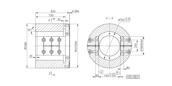
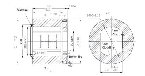
The inner bore’s arc surface (φ 700 mm) was treated with laser cladding, applying a wear-resistant alloy coating. The cladding layer achieved a hardness of 45–50 HRC with a depth of 2 mm, improving wear and impact resistance. Laser cladding was selected for its ability to deposit a high-quality, metallurgically bonded coating with minimal thermal distortion, ensuring durability under the dynamic loads of the rolling process.
Centering Mechanism
To address drive shaft instability, a centering mechanism was introduced. The bushing’s φ 500 mm arc surface was surface-quenched to serve as a centering reference. A centering ring was added to the work roll end face, designed to mate with the φ 500 mm arc surface, as shown in the optimized roll structure. This modification ensured precise alignment, reducing radial oscillations and minimizing wear.
Sealing Structure
To prevent cooling water ingress, a sealing ring was incorporated between the bushing end face and the work roll. One end of the seal was fixed to the bushing, while the other enveloped the work roll head. This design effectively prevented water from entering the bushing’s flat bore, reducing corrosion and associated wear.
Technical Specifications of Optimized Design
The optimized design incorporated specific technical parameters to ensure performance and compatibility with the steel mill’s operational requirements. The following table summarizes the key specifications:
| Component | Parameter | Specification |
|---|---|---|
| Inner Bore Flat Surface | Hardness | 45–50 HRC |
| Inner Bore Flat Surface | Quenching Depth | 2.0–2.5 mm |
| Arc Surface (φ 700 mm) | Laser Cladding Hardness | 45–50 HRC |
| Arc Surface (φ 700 mm) | Cladding Depth | 2 mm |
| Centering Arc Surface (φ 500 mm) | Surface Treatment | Surface Quenching |
| Sealing Structure | Material | Flexible Sealing Ring |
Implementation and Results
The optimized bushing was implemented in the steel mill’s hot rolling line, with performance monitored over an extended period. The results demonstrated significant improvements:
- Reduced Wear: The optimized bushing exhibited significantly lower wear rates, with the inner bore maintaining dimensional stability and eliminating tapered wear patterns.
- Improved Drive Stability: The centering mechanism and monolithic structure ensured precise alignment, eliminating drive shaft vibration and stabilizing equipment operation.
- Extended Service Life: The combination of surface hardening, laser cladding, and sealing extended the bushing’s service life, reducing replacement frequency.
- Lower Maintenance Costs: The elimination of liner bolts and reduced wear decreased maintenance interventions, lowering overall costs.
- Enhanced Equipment Reliability: The absence of bolt fractures and fillet cracks reduced downtime, preventing potential major equipment failures.
Conclusion
The optimization of the roller end bushing through structural enhancements and laser cladding with wear-resistant materials addressed the critical issues of wear, drive shaft instability, and frequent maintenance in the steel mill’s hot rolling process. The monolithic structure, surface hardening, laser cladding, centering mechanism, and sealing ring collectively improved durability, reduced maintenance costs, and met the steel mill’s operational demands. This systematic approach provides a reliable and cost-effective solution for similar applications in heavy industrial environments.