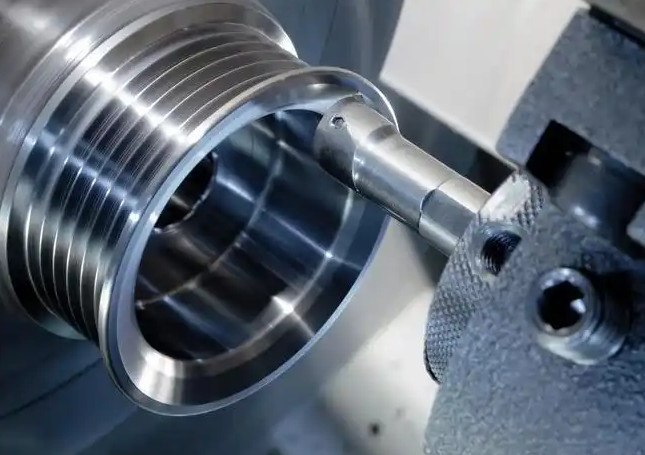
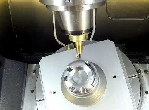
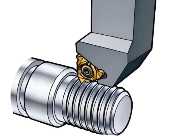
Milling, a critical process in modern manufacturing, relies on precision and stability to achieve high-quality outcomes. Tool vibration during milling can compromise surface finish, accelerate tool wear, and reduce machine longevity. Detecting and managing these vibrations is essential for maintaining machining efficiency and product quality. This guide provides a detailed, technical overview of methods and parameters for detecting tool vibration in milling processes, emphasizing practical implementation and measurable outcomes.
Understanding Tool Vibration in Milling
Tool vibration in milling arises from dynamic interactions between the cutting tool, workpiece, and machine tool. These vibrations are broadly categorized into forced vibrations and self-excited vibrations (chatter). Forced vibrations result from external factors such as unbalanced tools or interrupted cutting, while chatter stems from regenerative effects where the tool’s motion amplifies itself due to variations in chip thickness. Both types degrade machining performance, making detection a priority.
Vibration detection involves identifying the amplitude, frequency, and source of oscillations. Effective detection enables operators to adjust parameters, optimize tool paths, or implement damping strategies. The following sections detail established methods and key parameters for accurate vibration monitoring.

Methods for Detecting Tool Vibration
Several methods are employed to detect tool vibration, each leveraging specific sensors, signal processing techniques, and analysis tools. These methods are selected based on the machining environment, equipment availability, and precision requirements.
1. Vibration Sensor-Based Detection
Accelerometers are the most common sensors for detecting tool vibration due to their sensitivity and reliability. These devices measure acceleration in one or more axes, capturing vibrational signals from the tool or spindle. Piezoelectric accelerometers are particularly effective, offering high-frequency response and durability in harsh machining environments.
Implementation: Sensors are mounted on the spindle housing or tool holder to capture vibrations close to the cutting zone. Signals are amplified and recorded using data acquisition systems with sampling rates typically exceeding 10 kHz to capture high-frequency chatter. For example, a triaxial accelerometer can detect vibrations in X, Y, and Z directions, providing a comprehensive view of tool dynamics.
Parameters: Key parameters include:
- Frequency Range: 10 Hz to 10 kHz, covering typical milling vibration frequencies.
- Sensitivity: 100 mV/g for general-purpose accelerometers.
- Sampling Rate: Minimum 20 kHz to avoid aliasing in high-speed milling.
2. Acoustic Emission (AE) Monitoring
Acoustic emission sensors detect high-frequency stress waves generated by tool-workpiece interactions. AE signals are sensitive to micro-level changes, such as crack formation or tool wear, which often precede significant vibrations.
Implementation: AE sensors are typically mounted near the cutting zone. They operate in the frequency range of 100 kHz to 1 MHz, distinguishing them from lower-frequency vibration signals. Signal processing involves filtering to isolate AE events and correlating them with vibration patterns.
Parameters:
- Frequency Range: 100 kHz to 1 MHz.
- Threshold Level: Set at 40 dB to filter background noise.
- Sampling Rate: 2 MHz for high-resolution AE data.
3. Cutting Force Measurement
Vibration often manifests as fluctuations in cutting forces. Dynamometers measure these forces in real time, providing insights into tool stability. Piezoelectric dynamometers are widely used for their high accuracy and responsiveness.
Implementation: A dynamometer is integrated into the workpiece fixture or tool holder. It measures forces in multiple directions (e.g., Fx, Fy, Fz) during milling. Force signals are analyzed for periodic fluctuations indicative of vibration, often using Fast Fourier Transform (FFT) to identify dominant frequencies.
Parameters:
- Force Range: 0 to 5 kN for typical milling operations.
- Frequency Response: Up to 5 kHz for dynamic force measurement.
- Sensitivity: 5 pC/N for piezoelectric dynamometers.
4. Machine Vision-Based Detection
Machine vision systems use high-speed cameras to monitor tool motion or surface patterns. While less common, they are effective for detecting low-frequency vibrations or tool deflections visible on the workpiece surface.
Implementation: A high-speed camera with a frame rate of 1000 fps or higher is positioned to capture tool movement or surface texture. Image processing algorithms analyze pixel displacement to quantify vibration amplitude. This method is particularly useful for detecting vibrations in complex geometries.
Parameters:
- Frame Rate: 1000–5000 fps for high-speed milling.
- Resolution: Minimum 1280x720 pixels for clear imaging.
- Lighting: 5000 lumens to ensure image clarity.

Key Parameters Influencing Vibration Detection
Accurate vibration detection requires careful consideration of machining parameters that influence vibration behavior. These parameters are adjusted based on real-time data to minimize vibration and optimize performance.
| Parameter | Description | Typical Range | Impact on Vibration |
|---|---|---|---|
| Spindle Speed | Rotational speed of the tool (RPM) | 5000–20,000 RPM | High speeds may induce chatter if not matched to tool dynamics. |
| Feed Rate | Rate of tool advancement (mm/min) | 100–1000 mm/min | Excessive feed rates increase cutting forces, amplifying vibration. |
| Depth of Cut | Axial or radial cutting depth (mm) | 0.5–5 mm | Deeper cuts increase cutting forces, potentially triggering chatter. |
| Tool Geometry | Helix angle, rake angle, number of flutes | Helix: 30–45°; Flutes: 2–6 | Improper geometry can cause uneven chip load, leading to vibration. |
Signal Processing and Analysis Techniques
Raw sensor data requires processing to extract meaningful vibration information. The following techniques are commonly used to analyze signals and identify vibration characteristics.
1. Time-Domain Analysis
Time-domain analysis examines raw signal amplitude over time. Metrics such as root mean square (RMS) and peak-to-peak amplitude indicate vibration severity. For instance, an RMS value exceeding 0.5 g may suggest excessive vibration in high-speed milling.
Implementation: Data acquisition systems compute RMS and peak values in real time. Thresholds are set based on historical data or machine specifications to trigger alerts for abnormal vibrations.
2. Frequency-Domain Analysis
Frequency-domain analysis, primarily through FFT, identifies dominant vibration frequencies. This is critical for distinguishing forced vibrations (aligned with spindle speed) from chatter (related to tool-workpiece dynamics).
Implementation: FFT transforms time-domain signals into frequency spectra. Peaks at specific frequencies (e.g., spindle frequency or its harmonics) indicate vibration sources. Software tools like MATLAB or LabVIEW are used for real-time FFT analysis.
3. Time-Frequency Analysis
Time-frequency methods, such as Short-Time Fourier Transform (STFT) or wavelet transforms, analyze non-stationary signals where vibration characteristics change during machining.
Implementation: Wavelet transforms decompose signals into time-frequency components, revealing transient vibration events. This is particularly useful for detecting intermittent chatter in variable-depth milling.
Practical Implementation in CNC Milling
Implementing vibration detection in a CNC milling environment requires integrating sensors, data acquisition systems, and analysis software into the machining workflow. The following steps outline a systematic approach:
- Sensor Selection and Installation: Choose sensors (e.g., accelerometers, dynamometers) based on machining requirements. Mount sensors securely to minimize noise from machine vibrations.
- Data Acquisition Setup: Use a high-speed data acquisition system with a minimum sampling rate of 20 kHz. Ensure compatibility with sensor outputs (e.g., voltage or charge).
- Signal Processing: Implement real-time signal processing using software like LabVIEW or dedicated CNC monitoring systems. Configure filters to remove noise and focus on relevant frequency bands.
- Parameter Optimization: Adjust spindle speed, feed rate, and depth of cut based on vibration data. Use stability lobe diagrams to select chatter-free operating conditions.
- Continuous Monitoring: Establish thresholds for vibration metrics (e.g., RMS, frequency peaks) and integrate alerts into the CNC control system for real-time feedback.

Case Study: Vibration Detection in High-Speed Milling
In a high-speed milling operation on aluminum alloy (6061-T6), a triaxial accelerometer was mounted on the spindle to monitor vibrations. The setup included:
- Tool: 4-flute carbide end mill, 10 mm diameter, 30° helix angle.
- Machining Parameters: Spindle speed 12,000 RPM, feed rate 600 mm/min, axial depth of cut 2 mm.
- Sensor: Piezoelectric accelerometer, 100 mV/g sensitivity, 10 Hz–10 kHz frequency range.
- Data Acquisition: 20 kHz sampling rate, FFT analysis via MATLAB.
Analysis revealed a dominant frequency peak at 800 Hz, corresponding to chatter. By reducing the spindle speed to 10,000 RPM, the vibration amplitude dropped by 60%, improving surface finish and extending tool life.
Conclusion
Detecting tool vibration in milling processes is a multifaceted task requiring robust methods, precise parameters, and systematic implementation. Vibration sensors, acoustic emission monitoring, cutting force measurement, and machine vision provide complementary approaches to capture vibration data. By analyzing signals in the time, frequency, and time-frequency domains, manufacturers can identify vibration sources and optimize machining parameters. Practical integration of these methods into CNC milling systems ensures high precision, reduced tool wear, and enhanced productivity. This technical framework equips engineers with the tools to maintain stable and efficient milling operations.
