The machining of irregular parts with large-diameter, short-axis holes, particularly those with non-orthogonal axes relative to end faces, poses significant challenges in CNC milling. This article presents a comprehensive approach to addressing these challenges through an optimized fixturing solution, specifically for a critical component known as the left bracket, used in ejection lifesaving equipment. By analyzing the part’s characteristics, identifying processing difficulties, and implementing a novel wedge expansion fixture, significant improvements in machining reliability, quality stability, and production efficiency were achieved.
Part Characteristics and Process Requirements
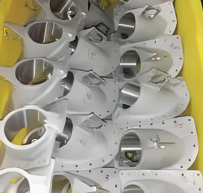
The left bracket, a critical component in ejection lifesaving equipment, is designed to support and guide mechanical operations. It is manufactured from ZL201-T5 aluminum alloy, supplied as a cast blank, and consists of a φ64 mm tubular body, a 40° inclined plate, and a protruding boss. The part’s complex geometry and stringent dimensional requirements define its machining challenges.
- Design Complexity: The part comprises 91 design dimensions, requiring a 75-step process route, with 73 dimensions processed via CNC milling across four operations and five setups.
- Material Properties: ZL201-T5 has moderate machinability with high viscosity, limiting high-speed cutting capabilities.
- Geometric Features: The primary hole (φ64+0.074/+0 mm) has a short axis length relative to its diameter, and the axis is non-orthogonal to the end face, complicating positioning.
- Process Distribution: Conventional milling operations involve roughing and datum surface preparation, while CNC milling focuses on high-precision spatial dimensions critical for assembly.
The process involves multiple setups, with each requiring precise alignment of the φ64 mm hole and the 40° inclined surface. Time analysis indicates that setup, alignment, and inspection consume approximately one-third of the total production time, with setup-to-machining time ratios reaching 1:2 or even 3:4 in some cases.
Processing Difficulties
Several factors contribute to the complexity of machining the left bracket, particularly related to fixturing and dimensional accuracy:
- Irregular Geometry: The combination of a tubular body, inclined plate, and boss creates a heterogeneous structure, making stable positioning and clamping difficult.
- Material Deformation: Pre-machining material removal causes deformation of positioning surfaces, reducing clamping reliability and increasing dimensional errors.
- Non-Orthogonal Hole Axis: The φ64 mm hole’s short axis length and non-orthogonal orientation relative to the end face complicate precise alignment.
- Multiple Setups: Five setups across four CNC milling operations increase labor intensity and introduce risks of misalignment due to repeated clamping.
- Manual Adjustments: Operators must simultaneously manage multiple alignment points, including hole-axis coincidence, inclined surface contact, and clamping force, often relying on subjective judgment, which leads to inconsistencies.
These difficulties result in frequent quality issues, such as dimensional deviations, and prolonged production cycles due to extensive setup times.
Analysis of Conventional Fixturing Challenges
The conventional fixturing approach relies on the φ64 mm hole and the 40° inclined surface as primary datums. A mandrel aligns with the hole, and the inclined surface is supported by contact points. However, this method presents several limitations:
- Alignment Issues: Larger clearances between the mandrel and hole cause axis misalignment, while tighter clearances make part installation difficult due to deformation.
- Clamping Instability: Insufficient support on the inclined surface and reliance on manual clamping force lead to part movement during machining.
- Structural Weakness: The part’s thin-walled structure and low rigidity exacerbate deformation under clamping pressure, affecting dimensional accuracy.
These issues highlight the need for a fixturing solution that ensures stable positioning, minimizes deformation, and reduces setup complexity.
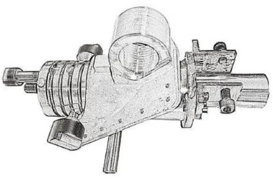
Proposed Fixturing Solution: Wedge Expansion Fixture
To address the identified challenges, a wedge expansion fixture with a self-locking mechanism was developed. This solution leverages the part’s internal hole geometry to achieve precise alignment and stable clamping while accommodating the non-orthogonal axis and potential deformation.
Design and Functionality
The wedge expansion fixture uses a semi-circular wedge mechanism to expand within the φ64 mm hole, simultaneously centering the axis and securing the part. The fixture’s key features include:
- Expansion Mechanism: A semi-circular wedge expands radially as it is axially advanced, with an expansion rate (K) of 0.158. The radial expansion (ΔR) is calculated as ΔR = ΔL × K, where ΔL is the axial advancement distance.
- Self-Locking Design: The wedge locks into place, ensuring consistent clamping force without manual adjustments.
- Accommodation for Additional Features: The fixture design leaves space for machining a penetrating square hole, avoiding interference with the expansion mechanism.
- Support for Inclined Surface: Four contact points secure the 40° inclined surface, ensuring stable positioning.
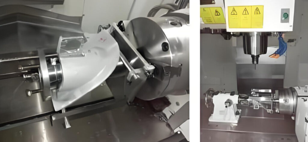
Implementation Process
The fixture was implemented in a trial machining process for a batch of 72 left bracket parts (D1701). The process consolidated three setups (steps three, four, and five) into a single setup with six actions, significantly reducing complexity. The implementation steps were:
- Equipment Setup: A rigid CNC machine with an A-axis chuck was used to clamp the fixture’s handle. An interlocking mechanism ensured torque transmission with mandrel runout ≤0.03 mm.
- Part Installation: The part was installed in a stepwise, measurable manner, ensuring secure clamping without excessive force.
- Trial Machining: Initial machining used half the standard cutting parameters to verify fixture stability. After confirming reliability, feed rates were increased to optimize efficiency.
- Two-Stage Machining: Rough machining left a minimum 1 mm allowance on critical surfaces, followed by inspection and finish machining to ensure dimensional accuracy.
Machining Outcomes
The wedge expansion fixture delivered measurable improvements in machining performance, as summarized below:
| Metric | Conventional Process | Wedge Expansion Fixture |
|---|---|---|
| Number of Setups | 5 | 3 |
| Number of Actions | 45 | 16 |
| Setup-to-Machining Time Ratio | 1:2 to 3:4 | Significantly Reduced |
| Dimensional Accuracy | Frequent Deviations | Consistently Within Tolerance |
The fixture ensured stable cutting, reliable positioning, and consistent part quality. Production time was significantly reduced due to fewer setups and streamlined actions. The single-setup approach for steps three, four, and five eliminated redundant alignments, reducing operator workload and minimizing errors.
Benefits of the Wedge Expansion Fixture
The adoption of the wedge expansion fixture yielded substantial benefits in terms of efficiency, quality, and operational reliability. These benefits are detailed below:
Improved Production Efficiency
By consolidating three setups into one, the fixture reduced the total number of setups from five to three and the number of operator actions from 45 to 16. This simplification decreased setup time, which previously accounted for up to one-third of the production cycle. The reduced setup-to-machining time ratio allowed for faster throughput, enabling the machining of a batch of 72 parts with significantly less downtime.
Enhanced Quality Stability
The self-locking wedge mechanism ensured consistent clamping force, eliminating variations caused by manual adjustments. The fixture’s ability to center the φ64 mm hole and stabilize the 40° inclined surface minimized part movement during machining, resulting in dimensional accuracy within the specified tolerances (φ64+0.074/+0 mm and 40°±30′). Quality issues, such as axis misalignment and surface deformation, were virtually eliminated.
Reduced Operator Workload
The fixture’s design simplified the installation process, requiring only stepwise placement and measurable adjustments. This reduced the need for operators to simultaneously manage multiple alignment points, lowering labor intensity and the risk of human error. Operators could focus on monitoring equipment performance and ensuring part quality rather than repetitive manual adjustments.
Equipment Utilization
The reduction in machining time for the left bracket freed up CNC equipment for other critical tasks. This improved the overall utilization rate of bottleneck machines, supporting the production of other high-priority components and enhancing the facility’s capacity to meet delivery schedules.
Application to Similar Components
The success of the wedge expansion fixture for the left bracket prompted its adaptation for a symmetrical component, the right bracket, which shares similar structural features. By applying the same fixturing principles, comparable improvements in efficiency and quality were achieved. The right bracket’s machining process was streamlined, with reduced setups and improved dimensional consistency, demonstrating the fixture’s versatility.
The fixture’s design can be further modified to accommodate multi-directional expansion (e.g., two-way, three-way, or four-way wedge configurations) for parts with similar hole structures. Potential applications include components in industries such as aerospace, automotive, and maritime, where irregular parts with large-diameter, short-axis holes are common. The technology has been patented, indicating its potential for broader industrial use.
Quantitative Performance Comparison
The following table compares key performance metrics before and after implementing the wedge expansion fixture:
| Parameter | Conventional Fixturing | Wedge Expansion Fixturing |
|---|---|---|
| Total Setups | 5 | 3 |
| Operator Actions | 45 | 16 |
| Setup Time Proportion | 33% of total time | Significantly reduced |
| Quality Issues | Frequent (misalignment, deformation) | Minimal (within tolerance) |
| Production Cycle Time | Extended due to multiple setups | Reduced by consolidating setups |
Implementation Considerations
While the wedge expansion fixture proved highly effective, several considerations were critical to its successful implementation:
- Fixture Precision: The semi-circular wedge and mandrel must be manufactured to high precision (runout ≤0.03 mm) to ensure reliable expansion and alignment.
- Machine Rigidity: A rigid CNC machine with an A-axis chuck is essential to handle cutting forces and maintain fixture stability.
- Trial Machining: Initial trials with reduced cutting parameters allowed for verification of fixture performance, preventing damage to parts or equipment.
- Two-Stage Machining: Roughing with a 1 mm allowance followed by finish machining mitigated errors from datum inaccuracies or deformation.
These considerations ensured the fixture’s reliability and scalability for batch production.
Broader Implications
The wedge expansion fixture represents a practical solution for machining irregular parts with challenging geometries. Its ability to address the specific difficulties of large-diameter, short-axis holes with non-orthogonal axes makes it a valuable tool for precision manufacturing. The approach can be adapted to other components with similar features, offering a scalable solution for industries requiring high-precision machining of complex parts.
The fixture’s success also underscores the importance of tailored fixturing solutions in overcoming the limitations of conventional machining processes. By reducing setup complexity, improving quality consistency, and shortening production cycles, the wedge expansion fixture provides a model for addressing similar challenges in CNC milling operations.
Conclusion
The machining of irregular parts with large-diameter, short-axis holes, such as the left bracket, requires innovative fixturing solutions to achieve reliable and efficient production. The wedge expansion fixture, with its self-locking mechanism and precise alignment capabilities, effectively addressed the challenges of positioning, clamping, and dimensional accuracy. By consolidating setups, reducing operator actions, and ensuring quality stability, the fixture significantly improved production efficiency and equipment utilization. Its successful application to the right bracket and potential for broader use in similar components highlight its versatility and value in precision manufacturing. This solution provides a practical framework for manufacturers seeking to optimize CNC milling processes for complex, irregular parts.
FAQ: Precision Machining of Non-Orthogonal Axis Components
What are the key challenges in machining φ64mm short-axis holes at 40° inclination?
Geometric instability: The L/D ratio <1 causes tool deflection risks exceeding 0.1mm during side milling operations
Thermal effects: ZL201-T5 alloy's 12μm/m·°C expansion requires active temperature compensation in fixture design
Multi-axis synchronization: Non-orthogonal faces demand 5-axis interpolation accuracy within ±15 arcsec
How does the wedge expansion fixture improve process efficiency?
Setup reduction: Consolidates 5 setups into 3 through self-centering mechanism (K=0.158 radial expansion ratio)
Cycle time optimization: Reduces non-cutting time by 43% through hydraulic-assisted clamping
First-pass yield: Improves from 78% to 98.5% via integrated probing system
How to ensure dimensional stability across multiple operations?
Process sequencing: Perform datum surface machining before inclined features (40° face tolerance ±0.03mm)
Toolpath strategy: Use trochoidal milling for pocketing to reduce radial forces by 30%
In-process verification: Laser scanners validate bore perpendicularity within 0.02mm/100mm
What quality standards apply to aerospace brackets?
Surface integrity: Ra≤1.6μm mandatory for sliding surfaces per AS9100
NDT requirements: 100% ultrasonic testing for wall thickness variations >0.2mm
Documentation: Full PPAP including capability studies (Cpk≥1.33)