
Precision machining of large aircraft components, such as vertical stabilizers, is critical to ensuring aircraft safety and longevity. Large parts present unique challenges due to their size and complexity, often leading to difficulties in achieving the required positional and machining accuracy. To address these issues, a specialized machine tool control system has been developed to enhance the accuracy and efficiency of vertical stabilizer machining. This article details the architecture, workflow, and technical implementation of this control system, focusing on its components, operational processes, and performance outcomes.
Introduction to Precision Machining Challenges
The machining of large aircraft components, such as vertical stabilizers, requires high precision to meet stringent safety and performance standards. The large dimensions and complex geometries of these parts complicate positioning and machining processes. Traditional methods often rely heavily on manual adjustments, which are time-consuming and prone to human error. To overcome these limitations, a control system integrating digital measurement and automation technologies has been designed. This system establishes a global aircraft coordinate system, enabling precise measurement of positioning points and improving both positional and machining accuracy.
Architecture of the Combined Machine Tool Control System
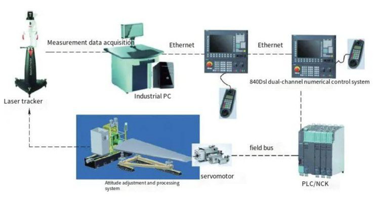
The control system for the specialized machine tool is a sophisticated assembly of hardware and software components designed to ensure precise positioning and machining. The system integrates advanced measurement tools, numerical control systems, and communication networks to achieve automated, high-precision operations. Below is a detailed breakdown of its key components.
Laser Tracker System
The laser tracker system is central to achieving high-precision measurements. It consists of a tracking head, control box, industrial PC, target sphere, and measurement accessories. Due to the large number of reference points required for vertical stabilizer positioning, manual measurement is inefficient. The system employs automated tracking based on a 3D model of the vertical stabilizer. During initial measurements, operators manually measure reference points to establish theoretical coordinates in the global aircraft coordinate system. Subsequent measurements use the laser tracker’s secondary development interface to automatically search for target spheres within a predefined spatial region. This automation accounts for manufacturing and installation errors by defining a search area centered on each reference point. Communication between the industrial PC and the laser tracker is facilitated through a dedicated interface, enabling parameter settings such as measurement mode, data acquisition frequency, and environmental factors.
Siemens 840Dsl CNC System
The Siemens 840Dsl CNC system serves as the control hub for both positioning and machining operations. It employs a Safety Programmable Logic (SPL) program to execute safety functions, using a secondary encoder (e.g., linear scale) or servo motor encoder as a safety encoder. The system supports dual-channel monitoring, with the SPL program running simultaneously in the PLC and NC systems for real-time synchronization. If inconsistencies are detected between PLC and NC signals, the system triggers an alarm, halts the servo axes, and disables servo torque output. To comply with safety standards, the system performs automatic safety function tests every 8 hours, ensuring reliable and secure operation.
Fieldbus and Industrial Ethernet
The control system utilizes a fieldbus for real-time control of field-level devices, such as relays, inverters, sensors, and actuators, which are interconnected via a network. Unlike point-to-point connections requiring extensive I/O interfaces, the fieldbus enables flexible communication with control devices. For upper-level monitoring, industrial Ethernet connects workshop and factory-level networks. A gateway (typically a serial port server) bridges the fieldbus and industrial Ethernet, allowing data from the fieldbus to be analyzed or manually adjusted via a computer. This setup supports real-time data acquisition from controllers, smart sensors, and measurement instruments, ensuring reliable and efficient communication.
Servo Motors
Servo motors drive the machine tool’s axes and positioning modules, operating under closed-loop control. This feedback mechanism compensates for errors in system components and motion, leveraging high-precision measurement devices to maintain accuracy. The closed-loop system ensures that deviations are corrected in real time, contributing to the overall precision of the machining process.
Industrial PC
The industrial PC manages the integration of automated measurements, data processing, core algorithms, simulation, and output generation. It oversees the control of electromechanical equipment and tooling, performing diagnostics, monitoring, and control tasks. The PC operates within the fieldbus structure, ensuring seamless communication with the laser tracker and other system components.
Workflow of the Vertical Stabilizer Control System
The control system operates through a structured workflow divided into five key stages: platform initialization, automatic positioning, manual positioning, clamping, and machining. Each stage is designed to ensure precise alignment and processing of the vertical stabilizer. The workflow is illustrated in the following table:
| Stage | Key Actions | Outcome |
|---|---|---|
| Platform Initialization | Initialize positioning platform, load vertical stabilizer, input theoretical and actual data, verify data accuracy. | Establishes target position and initial measurements. |
| Automatic Positioning | Plan positioning trajectory, simulate for interference, generate and execute positioning program. | Aligns stabilizer to target position or triggers manual adjustment. |
| Manual Positioning | Calculate position deviations, generate displacement instructions, perform manual adjustments, re-measure reference points. | Ensures precise alignment if automatic positioning is insufficient. |
| Clamping | Secure workpiece and transfer to machining area. | Prepares stabilizer for machining. |
| Machining | Align with on-machine probe, measure machining allowance, execute machining program, evaluate quality. | Produces finished part with verified accuracy. |
Platform Initialization
The process begins with initializing the positioning platform and loading the vertical stabilizer. Theoretical and actual position data are input, and accuracy is verified. If the data meets precision requirements, the actual position is set as the target. The measurement system is then initialized, measuring reference points to calculate the initial position and transformation parameters.
Automatic and Manual Positioning
Automatic positioning involves planning a trajectory and simulating it offline to detect potential collisions. If no interference is detected, a positioning program is generated and executed. Post-positioning, reference points are re-measured to verify accuracy. If accuracy is insufficient, the system calculates position deviations and determines whether manual positioning is needed. Manual adjustments are guided by displacement instructions, followed by re-measurement until the required accuracy is achieved. Once positioning is complete, the workpiece is clamped and moved to the machining area.
Machining Process
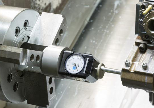
Machining begins with aligning the vertical stabilizer using an on-machine probe. A measurement program assesses machining allowances, followed by the generation and execution of a machining program. After machining, the part undergoes final inspection to evaluate quality. If accuracy requirements are not met, error analysis is conducted to identify and address issues.
Performance Outcomes
The control system significantly improves the machining process by reducing reliance on operator skills and minimizing downtime. Automated measurements and real-time feedback enable precise adjustments, reducing errors and auxiliary setup times. The system enhances positional accuracy to within specified tolerances, improves machining precision, and increases production efficiency. Additionally, it lowers scrap rates by ensuring consistent part dimensions and supports flexible batch production.
| Metric | Improvement |
|---|---|
| Positional Accuracy | Within ±0.05 mm (depending on part size) |
| Machining Precision | Meets aerospace tolerances (e.g., ±0.02 mm for critical features) |
| Production Efficiency | Reduced setup time by up to 30% |
| Scrap Rate | Decreased by approximately 15% |
Conclusion
The specialized machine tool control system for vertical stabilizer machining addresses critical challenges in large-part processing. By integrating laser tracking, CNC systems, servo motors, and networked communication, the system achieves high positional and machining accuracy. Its structured workflow ensures reliable operation, from initialization to final quality evaluation. The result is a significant improvement in precision, efficiency, and production flexibility, meeting the stringent demands of aerospace manufacturing.