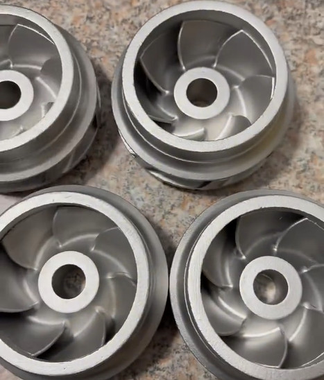
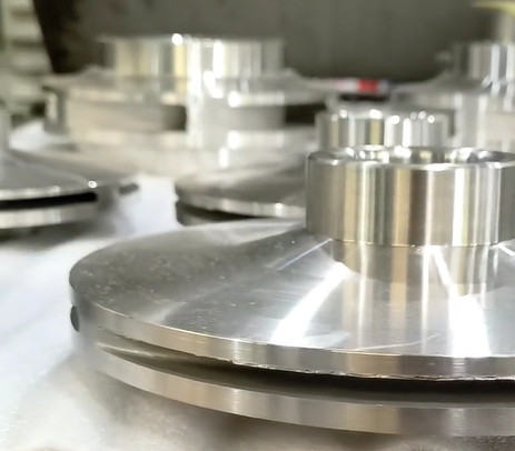
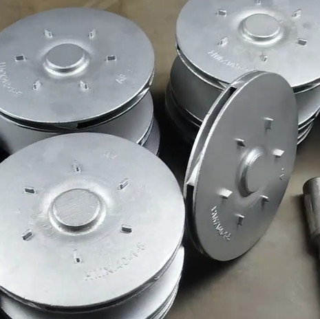
The investment casting process, also known as lost-wax casting, is widely used for manufacturing centrifugal impellers due to its ability to produce complex geometries with high precision and excellent surface finish. Centrifugal impellers, critical components in pumps and compressors, require stringent control to ensure performance, durability, and reliability. This article outlines five key control points in the investment casting process for centrifugal impellers, providing detailed parameters and technical insights to achieve consistent quality. Each control point is critical to minimizing defects and optimizing the impeller’s hydraulic and mechanical properties.
1. Wax Pattern Preparation
The first control point is the preparation of the wax pattern, which serves as the replica of the final impeller. The wax pattern’s dimensional accuracy and surface quality directly influence the cast impeller’s geometry. Any inconsistencies in the wax pattern can lead to defects such as dimensional deviations or surface irregularities in the final product.
Wax patterns are typically created by injecting molten wax into a metal die under controlled conditions. The die must be designed to account for the shrinkage of both the wax and the metal during cooling. For centrifugal impellers, which often feature thin, curved blades (0.7–2.0 mm thick), the die must ensure uniform wax flow to prevent incomplete filling or air entrapment.
| Parameter | Recommended Value | Purpose |
|---|---|---|
| Wax Injection Temperature | 60–70°C | Ensures proper flow and minimizes shrinkage |
| Injection Pressure | 0.3–0.5 MPa | Prevents air entrapment and ensures complete filling |
| Die Temperature | 20–30°C | Controls cooling rate and pattern dimensional stability |
After injection, the wax pattern is inspected for surface defects such as cracks, flow lines, or incomplete filling. Automated optical inspection systems can detect deviations as small as 0.05 mm. The wax pattern is then assembled onto a central wax sprue to form a tree-like structure, which facilitates the casting of multiple impellers in a single mold. Maintaining consistent wax properties, such as viscosity and thermal expansion, is essential to ensure repeatability.
Key Considerations: Variations in wax temperature or injection pressure can cause dimensional inaccuracies. For example, excessive pressure may lead to die wear, while insufficient pressure can result in incomplete filling, particularly in thin blade sections. Regular maintenance of the die and calibration of injection equipment are critical to achieving high-quality wax patterns.

2. Ceramic Shell Building
The second control point is the creation of the ceramic shell, which forms the mold for casting. The shell must withstand high temperatures (up to 1600°C) and provide sufficient strength to contain the molten metal. For centrifugal impellers, the shell’s thickness and uniformity are critical to preventing mold cracking or metal leakage during pouring.
The shell is built by repeatedly dipping the wax pattern assembly into a ceramic slurry, followed by stuccoing with fine sand or refractory particles. Each layer is dried under controlled conditions to ensure adhesion and prevent cracking. Typically, 6–10 layers are applied, resulting in a shell thickness of 5–8 mm. The slurry composition, often based on silica sol or water glass, affects the shell’s strength and dimensional accuracy.
Key Parameters:
- Slurry Viscosity: 20–30 seconds (Zahn Cup #4) to ensure uniform coating.
- Drying Time per Layer: 2–4 hours at 20–25°C and 50–60% relative humidity to prevent cracking.
- Stucco Particle Size: 0.1–0.5 mm for primary layers, 0.5–1.0 mm for backup layers to balance strength and permeability.
After the shell is built, it is dewaxed by heating in an autoclave at 150–200°C and 0.5–1.0 MPa to melt and remove the wax, leaving a hollow ceramic mold. The shell is then fired at 900–1100°C to enhance its strength and remove residual wax or organic matter. Inspection at this stage involves checking for cracks or weak spots, which can be detected using non-destructive testing methods such as X-ray or dye penetrant inspection.
Key Considerations: Inconsistent slurry viscosity or improper drying can lead to shell defects, such as delamination or porosity, which may cause metal leakage or inclusions in the casting. For complex impeller geometries, ensuring uniform shell thickness around thin blades is challenging but essential to avoid distortion during casting.
3. Molten Metal Pouring
The third control point is the pouring of molten metal into the ceramic shell. For centrifugal impellers, stainless steel (e.g., 17-4PH, 316L) or nickel-based alloys are commonly used due to their corrosion resistance and mechanical strength. The pouring process must be carefully controlled to ensure complete mold filling, minimize turbulence, and prevent defects such as shrinkage or gas porosity.
The pouring temperature and speed are critical parameters. For 17-4PH stainless steel, a pouring temperature of 1500–1550°C is recommended to ensure proper fluidity while avoiding excessive heat that could damage the shell. The pouring speed, typically 0.5–0.75 m/s, must be optimized to reduce turbulence and prevent air entrapment, particularly in the thin blade sections of the impeller.
| Parameter | Recommended Value | Purpose |
|---|---|---|
| Pouring Temperature | 1500–1550°C (17-4PH) | Ensures fluidity and minimizes shell damage |
| Pouring Speed | 0.5–0.75 m/s | Reduces turbulence and air entrapment |
| Mold Preheat Temperature | 800–1000°C | Prevents thermal shock and ensures complete filling |
The gating system, which directs the flow of molten metal into the mold, is designed to minimize turbulence and ensure directional solidification. For impellers, a top-gated system with risers is often used to provide additional metal to compensate for shrinkage. Simulation software, such as AnyCasting, can be employed to optimize the gating system and predict defect locations.
Key Considerations: Improper pouring parameters can lead to defects such as misruns (incomplete filling) or shrinkage porosity. For example, a study on 17-4PH impeller casting found that a pouring temperature below 1500°C caused premature solidification, leading to defects in thin blade sections. Maintaining consistent pouring conditions and using thermodynamic sensors to monitor temperature gradients can mitigate these issues.
4. Solidification and Cooling
The fourth control point is the solidification and cooling of the molten metal within the ceramic shell. Controlled solidification is essential to achieve a fine-grained microstructure, minimize shrinkage defects, and ensure the impeller’s mechanical properties, such as tensile strength and fatigue resistance.
Solidification is influenced by the cooling rate, which depends on the mold preheat temperature, shell thickness, and ambient conditions. For stainless steel impellers, a cooling rate of 10–20°C/min is typically targeted to promote directional solidification from the outer surface inward, reducing the risk of shrinkage cavities. The mold is often preheated to 800–1000°C to prevent thermal shock and ensure uniform cooling.
Key Parameters:
- Cooling Rate: 10–20°C/min to promote fine-grained microstructure.
- Shell Thickness: 5–8 mm to balance heat retention and cooling rate.
- Riser Design: 1.5–2.0 times the blade thickness to feed shrinkage.
After solidification, the casting is cooled to room temperature before the ceramic shell is removed. Rapid cooling can cause thermal stresses, leading to cracks, while excessively slow cooling may result in coarse grain structures, reducing mechanical strength. Post-solidification inspection, such as ultrasonic testing, is used to detect internal defects like shrinkage or porosity.
Key Considerations: Inadequate riser design or improper cooling rates can lead to shrinkage defects, particularly at the junction of blades and the hub. Simulation tools can predict solidification patterns and optimize riser placement to ensure defect-free castings.

5. Post-Casting Processing
The final control point is post-casting processing, which includes shell removal, finishing, and inspection. These steps ensure the impeller meets dimensional tolerances, surface quality, and performance requirements. For centrifugal impellers, post-processing is critical to achieving tight tolerances (e.g., ±0.05 mm) and balancing the impeller for high-speed rotation.
The ceramic shell is removed using mechanical methods such as vibration, hammering, or high-pressure water jetting. The casting is then cleaned via shot blasting to remove residual shell material and achieve a surface finish of Ra 3.2–6.3 µm. Excess material, such as sprues and risers, is cut off using grinding or CNC machining.
Key Parameters:
- Surface Finish: Ra 3.2–6.3 µm for hydraulic efficiency.
- Dimensional Tolerance: ±0.05 mm for blade thickness and hub diameter.
- Dynamic Balancing: G2.5 grade (ISO 1940) for rotational stability.
Final inspection involves dimensional checks using coordinate measuring machines (CMM), non-destructive testing (e.g., X-ray, dye penetrant), and dynamic balancing to ensure the impeller operates without vibration at high speeds (e.g., 3000 rpm). Heat treatment, such as solution annealing at 1040°C for 17-4PH stainless steel, may be applied to enhance mechanical properties.
Key Considerations: Incomplete shell removal or improper machining can affect the impeller’s hydraulic performance or balance. For example, residual shell material in blade passages can disrupt fluid flow, reducing pump efficiency. Rigorous inspection protocols are essential to ensure compliance with industry standards.
Conclusion
The investment casting of centrifugal impellers is a complex process requiring precise control at every stage. The five critical control points—wax pattern preparation, ceramic shell building, molten metal pouring, solidification and cooling, and post-casting processing—each play a vital role in achieving high-quality castings. By adhering to the recommended parameters and addressing potential issues, manufacturers can produce impellers with superior dimensional accuracy, surface finish, and mechanical properties. This systematic approach ensures reliable performance in demanding applications such as pumps and compressors.
