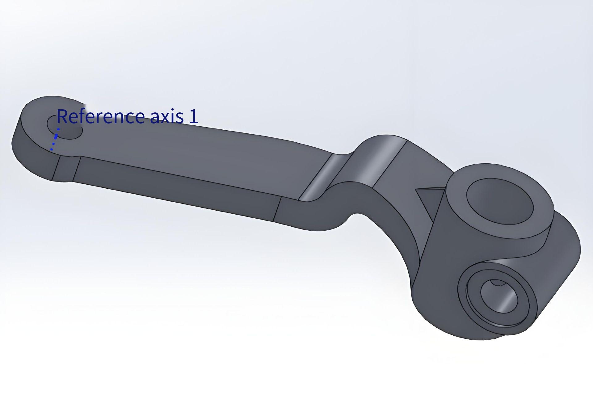
The manufacturing of torque arm components for aircraft landing gear presents significant demands for precision, efficiency, and adaptability in CNC machining processes. This article outlines the design and implementation of a flexible CNC fixture system tailored for torque arm parts. By integrating modular positioning, quick-change mechanisms, and zero-point clamping, the system addresses the need for rapid setup, high precision, and compatibility with multiple part variants. The solution leverages a combination fixture approach built on a CNC machining platform, incorporating a precision hole-system base plate, interchangeable expanding mandrels, modular positioning supports, and ball-lock quick-connect systems. The result is a robust, efficient, and flexible preparation scheme for CNC machining of torque arm components.
Design Objectives and System Overview
The primary objective of the fixture design is to enable flexible positioning and clamping of torque arm components while facilitating rapid integration with CNC machine tools. The system is built on a combination fixture philosophy, utilizing standardized components to accommodate parts with similar geometries. Key components include:
- Precision Hole-System Base Plate: A matrix-structured base plate with positioning holes maintaining a tolerance of ±0.01 mm for high-precision modular assembly.
- Interchangeable Expanding Mandrels: Elastic centering and clamping structures with minimal clamping stroke and high centering accuracy.
- Modular Positioning Supports: Adjustable and fixed supports that connect to the base plate for precise part alignment.
- Ball-Lock Quick-Connect System: Ensures rapid and repeatable fixture-to-pallet connection with a positioning accuracy of ±0.013 mm.
- Zero-Point Positioning System: Enables quick fixture-to-machine connection, minimizing setup time.
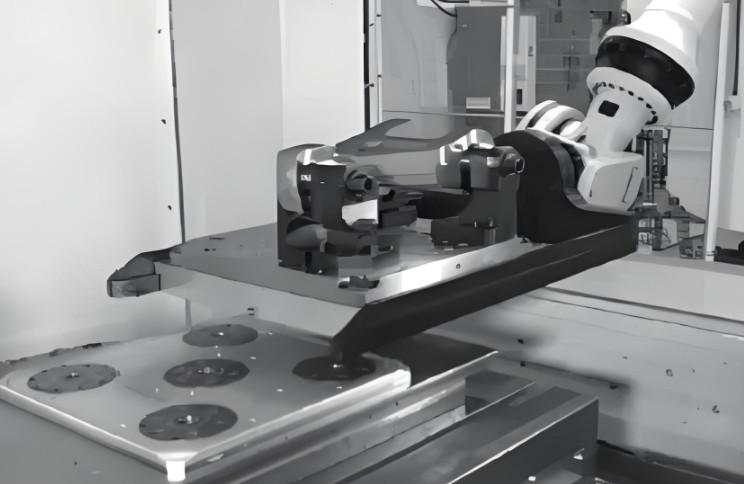
This system allows offline part setup, robotic transport to the machining line, and seamless integration with CNC machines, significantly reducing auxiliary setup times and enhancing machine utilization.
Technical Challenges in CNC Machining of Torque Arm Components
Traditional CNC machining processes for torque arm components face several limitations that hinder efficiency:
- High Setup Times: Conventional fixtures require manual positioning and alignment, consuming significant preparation time.
- Limited Flexibility: One-to-one fixture designs lack adaptability for multiple part variants, necessitating dedicated fixtures for each part type.
- Low Machine Utilization: Prolonged setup and changeover times reduce the effective cutting time of CNC machine spindles.
- Inconsistent Precision: Manual clamping methods introduce variability in positioning accuracy, affecting machining quality.
The proposed flexible fixture system addresses these issues by standardizing components, enabling rapid changeovers, and ensuring high repeatability in positioning and clamping.
Fixture Design and Component Details
The flexible CNC fixture system is designed to accommodate the geometric and machining requirements of torque arm components. Below are the key components and their technical specifications:
Expanding Mandrel Structure
The expanding mandrel is a critical component for precise positioning and clamping. Its elastic centering design eliminates clearance during positioning, ensuring high accuracy. Key features include:
- Clamping Stroke: Minimal stroke to reduce setup time while maintaining secure clamping.
- Centering Accuracy: Achieves high precision by eliminating positional gaps, stabilizing the part during machining.
- Dual Functionality: Combines positioning and clamping, reducing the number of components needed.
The mandrel’s design enhances machining stability, contributing to improved surface finish and dimensional accuracy of the torque arm components.
Modular Positioning Supports
The positioning supports are designed for flexibility and precision. They consist of fixed and adjustable supports mounted on the hole-system base plate. Technical details include:
- Fixed Supports: Two fixed supports are secured to the base plate using screws and dowel pins, ensuring rigid alignment based on the part’s process dimensions.
- Adjustable Supports: One adjustable support allows axial movement to accommodate slight variations in part geometry, locked in place with a limit pin.
- Connection Method: Supports are mounted on the base plate with a hole tolerance of ±0.01 mm, ensuring precise assembly.
This modular approach allows the fixture to adapt to parts with similar external profiles, reducing the need for dedicated fixtures.
Hole-System Base Plate
The base plate serves as the foundation for the fixture system, providing a standardized interface for mounting positioning supports and mandrels. Specifications include:
- Matrix Hole Structure: A grid of positioning holes with a center-to-center tolerance of ±0.01 mm.
- Material: High-strength steel to ensure durability and dimensional stability under machining forces.
- Compatibility: Designed to interface with the fixture pallet and zero-point positioning system.
The precision hole system ensures repeatable and accurate placement of modular components, facilitating rapid fixture assembly.
Ball-Lock Quick-Connect System
The ball-lock system enables rapid and secure attachment of the base plate to the fixture pallet. Key specifications are:
- Repeatability: Positioning accuracy of ±0.013 mm, ensuring consistent fixture alignment.
- Connection Time: Assembly and disassembly completed in approximately 1 minute.
- Construction: Off-the-shelf precision ball-lock components integrated into the fixture pallet.
This system minimizes changeover time, allowing multiple fixtures to be prepared offline and quickly swapped on the production line.
Zero-Point Positioning System
The zero-point system facilitates rapid connection between the fixture pallet and the CNC machine. Its features include:
- Positioning Accuracy: Maintains alignment within ±0.013 mm, eliminating the need for manual realignment.
- Connection Time: Offline setup and machine connection completed in under 0.5 hours.
- Interface: Zero-point connectors mounted on the pallet base align with corresponding machine table receptors.
This system maximizes machine uptime by enabling seamless transitions between different part setups.
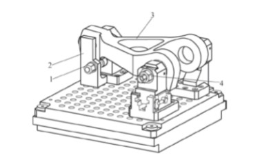
Assembly and Clamping Process
The assembly and clamping process for torque arm components is streamlined to minimize setup time and ensure precision. The steps are as follows:
- Fixture Preparation: Select appropriate expanding mandrels and positioning supports based on the torque arm’s dimensions.
- Base Plate Assembly: Mount two fixed positioning supports and two expanding mandrels onto the hole-system base plate, aligning with designated holes.
- Adjustable Support Setup: Install the adjustable support and one additional mandrel, securing with screws and dowel pins.
- Part Installation: Remove the limit pin, slide the adjustable support to its maximum extent, and insert the torque arm into the two fixed mandrels, ensuring the part’s hole end faces contact the fixed supports.
- Final Positioning: Slide the adjustable support to align with the part’s third hole, insert the limit pin, and engage the third mandrel.
- Clamping: Tighten two locknuts to secure the mandrels, with an auxiliary pressure plate providing additional clamping force.
- Machine Integration: Transport the assembled fixture via robot to the CNC machine, where the zero-point system ensures rapid connection without further alignment.
This process, illustrated in the referenced figures, ensures that parts are securely clamped and precisely positioned for machining, with offline setup reducing machine downtime.
Performance Outcomes
The implementation of the flexible CNC fixture system has yielded measurable improvements in production efficiency. Key outcomes are summarized in the table below:
| Performance Metric | Outcome |
|---|---|
| Fixture Changeover Time | Reduced to approximately 1 minute using ball-lock system |
| Offline Setup Time | Less than 0.5 hours per part |
| Machine Utilization Rate | Increased due to minimized setup and alignment times |
| Fixture Manufacturing Cost | Reduced through standardized hole-system base plate and modular components |
| Positioning Accuracy | Maintained within ±0.013 mm using zero-point and ball-lock systems |
These outcomes demonstrate the system’s ability to enhance efficiency, reduce costs, and maintain high precision across multiple part variants.
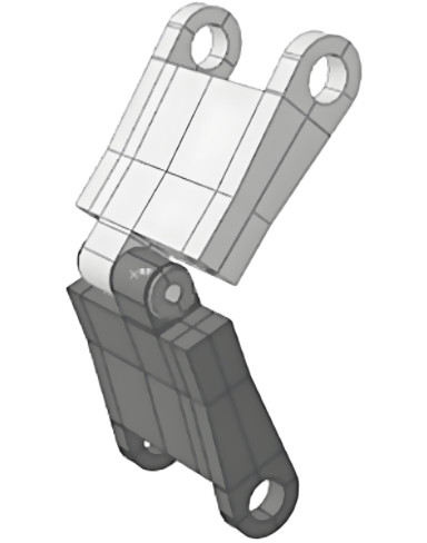
Practical Applications and Scalability
The flexible fixture system is particularly suited for small-batch, multi-variant production, such as aircraft landing gear components. Its modular design allows adaptation to parts with similar geometries by adjusting the positioning supports and mandrels on the base plate. The system’s compatibility with automated production lines, facilitated by robotic transport and zero-point positioning, makes it scalable for high-mix manufacturing environments. The standardized base plate and quick-connect systems also reduce the need for custom fixtures, lowering long-term manufacturing costs.
Conclusion
The flexible CNC fixture system for torque arm components represents a significant advancement in addressing the limitations of traditional fixturing methods. By integrating modular positioning, expanding mandrels, precision hole-system base plates, ball-lock quick-connects, and zero-point positioning, the system achieves rapid setup, high precision, and adaptability to multiple part variants. The design reduces auxiliary setup times, increases CNC machine utilization, and lowers fixture manufacturing costs. Its successful application in torque arm production provides a technical foundation for broader adoption of flexible fixturing in CNC machining, supporting the industry’s move toward automation and efficiency.