
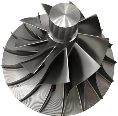
Turbine blades are critical components in turbochargers, directly impacting performance. Traditional blade manufacturing methods, such as precision casting and forging, have limitations. Precision casting requires minimal machining but is unsuitable for high-expansion-ratio turbochargers, while forging demands extensive machining with high costs. This article explores a four-axis machining approach for processing precision-forged turbine blades, focusing on flash removal at the leading and trailing edges. By designing a specialized fixture and developing a four-axis machining program using UG software, this method achieves a 78% cost reduction compared to five-axis machining, with improved efficiency and precision.
Background and Problem Statement
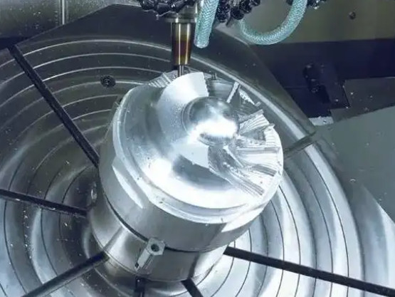
Turbine blades in high-performance turbochargers require high precision and durability, especially for applications with expansion ratios up to 6.0. Precision-forged blades, while offering superior material properties, leave a 4mm flash at the leading and trailing edges that must be removed. Traditionally, five-axis machining centers were used to mill the blade surface, but this approach is costly due to high tool wear, low efficiency, and expensive machine operation. Four-axis machining offers a cost-effective alternative, with machining costs approximately one-fifth of five-axis systems. This study addresses the challenges of machining complex blade surfaces using a four-axis machining center, focusing on fixture design and programming.
Materials and Equipment
The machining process involves specific materials, equipment, and software tailored to the blade's geometry and material properties.
Blade Blank
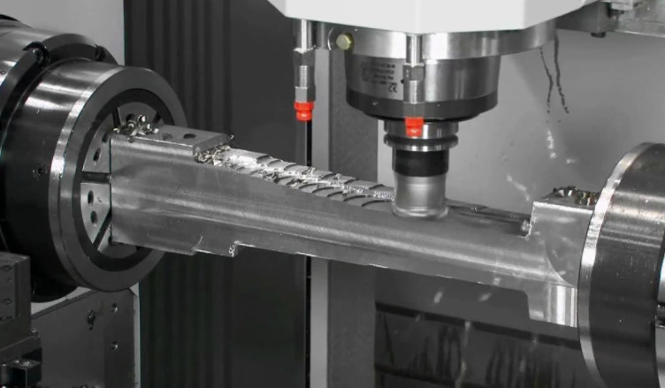
The turbine blade blank is precision-forged from a high-temperature alloy, with the blade surface formed to near-final shape. A 4mm flash remains at the leading and trailing edges, and a 5mm-long, R5mm process positioning point is included for fixturing. The blade's thin, curved geometry and high-temperature alloy composition pose machining challenges, including deformation and rigidity issues.
Machine Tool
A DMG MORI DMC63V vertical machining center, upgraded with a fourth rotary axis (A-axis), is used. The machine operates with a FANUC 0i MD control system, enabling precise four-axis linkage for complex surface machining.
Tools
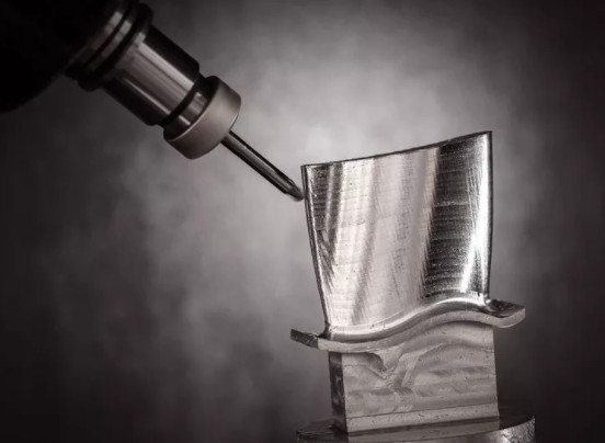
An 8mm ball-end milling cutter (Blue Banner LC630T 45A) is selected for rough and finish machining. The tool’s geometry minimizes interference with the fixture and ensures smooth machining of the blade’s curved edges.
Software
UG software is employed for fixture design, 3D modeling, assembly verification, 2D drawing generation, machining program development, and toolpath simulation. Its multi-axis machining module ensures accurate programming for complex surfaces.
Fixture Design for Four-Axis Machining
The fixture design is critical to achieving precise and stable machining of the turbine blade. The following sections detail the design considerations and solutions.
Processing State Analysis
The blade’s geometry and material properties present several challenges:
- The blade surface is entirely composed of curves and inclined planes, complicating positioning accuracy.
- Small process positioning points (R5mm, 5mm long) are insufficient for primary clamping but can assist in alignment.
- Precision forging introduces irregular stress relaxation, causing deviations up to 0.15mm between the blank and design model.
- The blade’s thin structure and high-temperature alloy material result in low rigidity during machining.
- The leading and trailing edges require four-axis linkage to machine complex spatial curves with smooth transitions.
- The fixture must avoid tool interference while maintaining rotational alignment with the blade’s centerline.
- The fixture’s rigidity and connection to the machine’s rotary axis must withstand extended overhang.
Fixture Design Solutions
The fixture is designed to address these challenges through the following features:
- Rotary Structure: A cylindrical fixture body ensures rotational capability and includes alignment features for the rotary axis. It connects to the machine’s chuck and tailstock for rigid, efficient setup.
- V-Shaped Positioning Slots: Two V-shaped slots align with the blade’s process positioning points, ensuring accurate rotational axis alignment. Copper inserts prevent over-constraint.
- Main Positioning Reference: The blade’s large-end tenon slot conical surfaces, identified as the most dimensionally stable area, serve as the primary positioning reference. A matching groove with axial positioning bosses ensures radial and axial stability.
- Clamping Mechanism: An upper mold with threaded bolts secures the blade, compensating for deformation and ensuring firm clamping without interfering with the toolpath.
- Auxiliary Support Surface: A support surface, machined to match the blade’s back curve, corrects deformation up to 0.15mm and enhances rigidity during machining.
The fixture’s design ensures precise positioning, reliable clamping, and compatibility with four-axis machining, minimizing errors and improving surface quality.
Machining Program Development
The four-axis machining program is developed using UG software to ensure precise toolpaths and efficient flash removal. The process involves several steps:
Setting the Machining Coordinate System (MCS)
The MCS is established at the center of the blade’s tenon base, aligned with the rotary table’s A-axis. The X-axis zero point is offset to the fixture’s rear face to simplify coordinate setup during machining.
Creating Drive Surfaces
To optimize toolpaths, two auxiliary drive surfaces are created in UG’s multi-axis machining module. These surfaces match the curvature of the blade’s leading and trailing edges and extend beyond the flash area to ensure complete coverage without machining the entire blade surface.
Tool Parameter Configuration
An 8mm ball-end milling cutter is defined in UG with parameters matching the physical tool. Accurate tool settings are critical to generating reliable toolpaths.
Programming Parameters
Key programming settings include:
| Parameter | Setting |
|---|---|
| Workpiece Body | Blade design model (not blank model) |
| Drive Surface | Auxiliary programming surfaces |
| Projection Vector | Perpendicular to drive surface |
| Tool Axis | Relative to drive surface, side tilt 20°, rotation -10°, no forward tilt |
| Rotary Axis | X-axis |
These settings optimize tool life by avoiding center cutting and prevent fixture interference.
Program Simulation and Verification
Toolpaths are simulated in UG to verify accuracy. The simulation includes toolpath playback, 3D machining visualization, and overcut detection to ensure the program meets design requirements.
Results and Performance
The four-axis machining approach, supported by the custom fixture and UG programming, achieved significant improvements:
- Cost Reduction: Machining costs were reduced by 78% compared to five-axis machining, primarily due to lower machine operating costs and reduced tool wear.
- Efficiency: Processing time was reduced by approximately 2.5 times, shortening production cycles.
- Precision: Scanned trial blades confirmed that all technical parameters met design requirements, with consistent quality suitable for mass production.
- Stability: The fixture’s design and auxiliary support surfaces ensured reliable clamping and minimal deformation, improving surface quality.
The following table summarizes the performance comparison:
| Metric | Four-Axis Machining | Five-Axis Machining |
|---|---|---|
| Cost Reduction | 78% | Baseline |
| Efficiency Improvement | 2.5x | Baseline |
| Precision | Meets design requirements | Meets design requirements |
| Production Stability | High (mass production) | Moderate |
Conclusion
The development of a four-axis machining process for turbine blade flash removal, supported by a custom-designed fixture and UG software programming, addresses the limitations of five-axis machining. The fixture ensures accurate positioning and reliable clamping, while the programming approach optimizes toolpaths for efficiency and precision. This method achieves a 78% cost reduction and 2.5 times higher efficiency compared to five-axis machining, with consistent quality validated through trial production. The approach provides a scalable solution for high-performance turbine blade manufacturing, offering valuable insights for similar machining applications.