
Gearboxes are essential components in various mechanical systems, including automotive transmissions, industrial machinery, and renewable energy systems. Their primary function—transmitting power and adjusting torque—requires exceptional precision, durability, and material strength. The production of gearbox components, such as gears, shafts, and housings, relies on CNC (Computer Numerical Control) machining to meet tight tolerances, complex geometries, and consistent quality standards. This article explores the materials commonly used in gearbox manufacturing, the CNC machining processes involved, and the precision requirements crucial for optimal performance. It also provides practical insights and parameters useful for engineers and manufacturers in the field.
Material Selection for Gearbox Components
The choice of materials for gearbox components prototype is driven by factors such as load-bearing capacity, wear resistance, fatigue strength, and environmental conditions. Gears, shafts, and housings each have distinct material requirements, balanced against cost and manufacturability.
Gear Materials
Gears are subjected to high stresses, sliding contact, and cyclic loading, necessitating materials with excellent strength, hardness, and toughness. Common materials include:
- Alloy Steels: Grades like AISI 4140, 4340, and 8620 are widely used due to their high strength and hardenability. After heat treatment, these steels achieve surface hardness of 55–60 HRC, ideal for heavy-duty gears.
- Carburizing Steels: Low-carbon steels like AISI 1018 or 20MnCr5 are carburized to create a hard surface (58–62 HRC) while maintaining a tough core, suitable for automotive gears.
- Stainless Steels: Grades like 17-4 PH or 316 are used in corrosive environments, such as marine or chemical applications, with hardness ranging from 35–45 HRC.
- Cast Iron: Nodular cast iron (e.g., ASTM A536) is used for large, low-speed gears due to its damping properties and cost-effectiveness.
Key considerations include ensuring uniform microstructure to prevent cracking during machining and selecting materials compatible with heat treatment processes like quenching or nitriding.
Shaft Materials
Shafts require high fatigue resistance and torsional strength to transmit power effectively. Common materials include:
- Medium-Carbon Steels: AISI 1045 or 4140, heat-treated to 30–40 HRC, are cost-effective for industrial shafts.
- Alloy Steels: AISI 4340 or 42CrMo4, with tensile strengths of 900–1200 MPa, are used for high-load applications like wind turbine shafts.
- Stainless Steels: 316L or 420 are selected for corrosion-resistant shafts, with hardness of 25–35 HRC.
Shafts are often normalized or annealed before machining to reduce internal stresses and improve machinability.
Housing Materials
Gearbox housings provide structural support and alignment for gears and shafts, requiring dimensional stability and vibration damping. Common materials include:
- Cast Iron: Gray cast iron (e.g., ASTM A48) or ductile iron is favored for its damping properties and ease of casting complex shapes.
- Aluminum Alloys: Alloys like A356 or 6061-T6 are used in lightweight applications, such as automotive gearboxes, with tensile strengths of 200–300 MPa.
- Steel Alloys: Welded or forged steel (e.g., AISI 1045) is used for high-strength housings in heavy machinery.
Housings are typically cast or forged, then machined to achieve precise bearing seats and mounting surfaces.

CNC Machining Processes for Gearbox Components
CNC machining is the backbone of gearbox manufacturing, enabling the production of components with intricate geometries and tolerances as tight as ±0.005 mm. The primary processes include turning, milling, hobbing, grinding, and drilling, often performed on multi-axis CNC machines for efficiency and accuracy.
Machining Gears
Gears require precise tooth profiles and surface finishes to ensure smooth meshing and minimal wear. The machining process involves multiple stages:
- Blank Preparation: A cylindrical blank is turned on a CNC lathe to the gear’s outer diameter. For a 100 mm diameter AISI 4140 gear, use a cutting speed of 80–120 m/min, feed rate of 0.2–0.4 mm/rev, and depth of cut of 1–2 mm.
- Gear Hobbing: A CNC hobbing machine cuts the tooth profile using a hob. For a spur gear with a module of 2, set a cutting speed of 60–100 m/min and a feed rate of 1–2 mm/rev. Tolerances for tooth thickness are typically ±0.01 mm.
- Heat Treatment: Gears are carburized or induction-hardened to achieve surface hardness of 58–62 HRC, followed by tempering to reduce brittleness.
- Finish Grinding: CNC gear grinding refines the tooth profile to a surface finish of Ra 0.4–0.8 µm and a profile accuracy of ISO 5–6. Grinding parameters include a wheel speed of 30–40 m/min and a feed rate of 0.01–0.02 mm/pass.
- Inspection: Gear geometry is verified using a CNC gear measuring machine, checking parameters like pitch error (±0.005 mm) and profile deviation (±0.003 mm).
For complex gears like helical or bevel gears, 5-axis CNC milling or specialized gear-shaping machines are used to achieve the required helix angles or conical profiles.
Machining Shafts
Shafts must be machined to precise diameters and lengths to ensure proper bearing fit and alignment. The process includes:
- Rough Turning: A CNC lathe shapes the shaft’s outer diameter. For a 50 mm diameter AISI 1045 shaft, use a cutting speed of 100–150 m/min, feed rate of 0.3–0.5 mm/rev, and depth of cut of 2–3 mm.
- Keyway Milling: Keyways for torque transmission are milled using a CNC milling machine with a side-and-face cutter. Maintain a width tolerance of ±0.01 mm.
- Splining: Splines are machined using a CNC spline hobbing or broaching machine, with a cutting speed of 50–80 m/min and a feed rate of 0.1–0.2 mm/rev.
- Finish Turning/Grinding: Bearing surfaces are turned or ground to a diameter tolerance of ±0.005 mm and a surface finish of Ra 0.4 µm. Grinding parameters include a wheel speed of 25–35 m/min and a feed rate of 0.01–0.015 mm/pass.
- Heat Treatment: Shafts are quenched and tempered to achieve hardness of 30–40 HRC, followed by straightening to correct any distortion.
Slender shafts require steady rests to prevent deflection during machining, and coolant is used to minimize thermal distortion.
Machining Housings
Gearbox housings prototyping require precise machining of bearing seats, mounting surfaces, and alignment features. The process includes:
- Rough Milling: A CNC milling machine removes excess material from cast or forged blanks. For a gray cast iron housing, use a cutting speed of 120–180 m/min, feed rate of 0.2–0.4 mm/tooth, and depth of cut of 2–4 mm.
- Boring: Bearing seats are bored to a diameter tolerance of ±0.01 mm using a CNC boring tool. Boring parameters include a cutting speed of 80–120 m/min and a feed rate of 0.1–0.2 mm/rev.
- Drilling and Tapping: Bolt holes are drilled and tapped for assembly. For M10 threads, use a cutting speed of 30–50 m/min and a feed rate synchronized with the thread pitch.
- Finish Milling: Mounting surfaces are milled to a flatness tolerance of ±0.02 mm and a surface finish of Ra 1.6 µm. Milling parameters include a cutting speed of 100–150 m/min and a feed rate of 0.1–0.2 mm/tooth.
- Inspection: A Coordinate Measuring Machine (CMM) verifies critical dimensions, such as bearing seat alignment (±0.015 mm) and surface flatness.
Rigid fixturing is essential to prevent vibration during heavy material removal, and coolant is applied to control dust and heat in cast iron machining.
Precision Requirements in Gearbox Manufacturing
Precision is paramount in gearbox manufacturing, as even minor deviations can lead to noise, vibration, or premature failure. Tolerances, surface finishes, and quality control measures are tailored to each component’s function.
Gear Precision
Gears must adhere to strict standards, such as ISO 1328 or AGMA, to ensure smooth operation and load distribution. Key precision requirements include:
- Tooth Profile Accuracy: Profile deviations must be within ±0.003 mm (ISO 5–6) to minimize contact errors.
- Pitch Error: Cumulative pitch error should not exceed ±0.005 mm to ensure consistent meshing.
- Surface Finish: Tooth surfaces require a finish of Ra 0.4–0.8 µm to reduce friction and wear.
- Runout: Radial runout must be within ±0.01 mm to prevent vibration.
CNC gear grinders and measuring machines are used to achieve and verify these tolerances, with in-process inspections to detect deviations early.
Shaft Precision
Shafts require precise diameters, straightness, and surface finishes to ensure proper bearing fit and alignment. Key requirements include:
- Diameter Tolerance: Bearing surfaces must be within ±0.005 mm to ensure a secure fit.
- Straightness: Shafts must maintain straightness within 0.01 mm/m to avoid misalignment.
- Surface Finish: Bearing surfaces require a finish of Ra 0.4 µm to minimize friction.
- Keyway Tolerance: Keyway width must be within ±0.01 mm for reliable torque transmission.
CMM and laser alignment tools are used to verify shaft geometry, with particular attention to concentricity and runout.
Housing Precision
Housings must maintain precise alignment and flatness to support gears and shafts. Key requirements include:
- Bearing Seat Tolerance: Diameter tolerances of ±0.01 mm ensure proper bearing installation.
- Flatness: Mounting surfaces must be flat within ±0.02 mm to prevent misalignment.
- Surface Finish: Bearing seats and mounting surfaces require a finish of Ra 1.6 µm for reliable assembly.
- Alignment: Bearing seat alignment must be within ±0.015 mm to ensure parallel shaft operation.
Precision boring and milling, combined with CMM inspections, ensure housing accuracy, with fixturing designed to minimize distortion during machining.
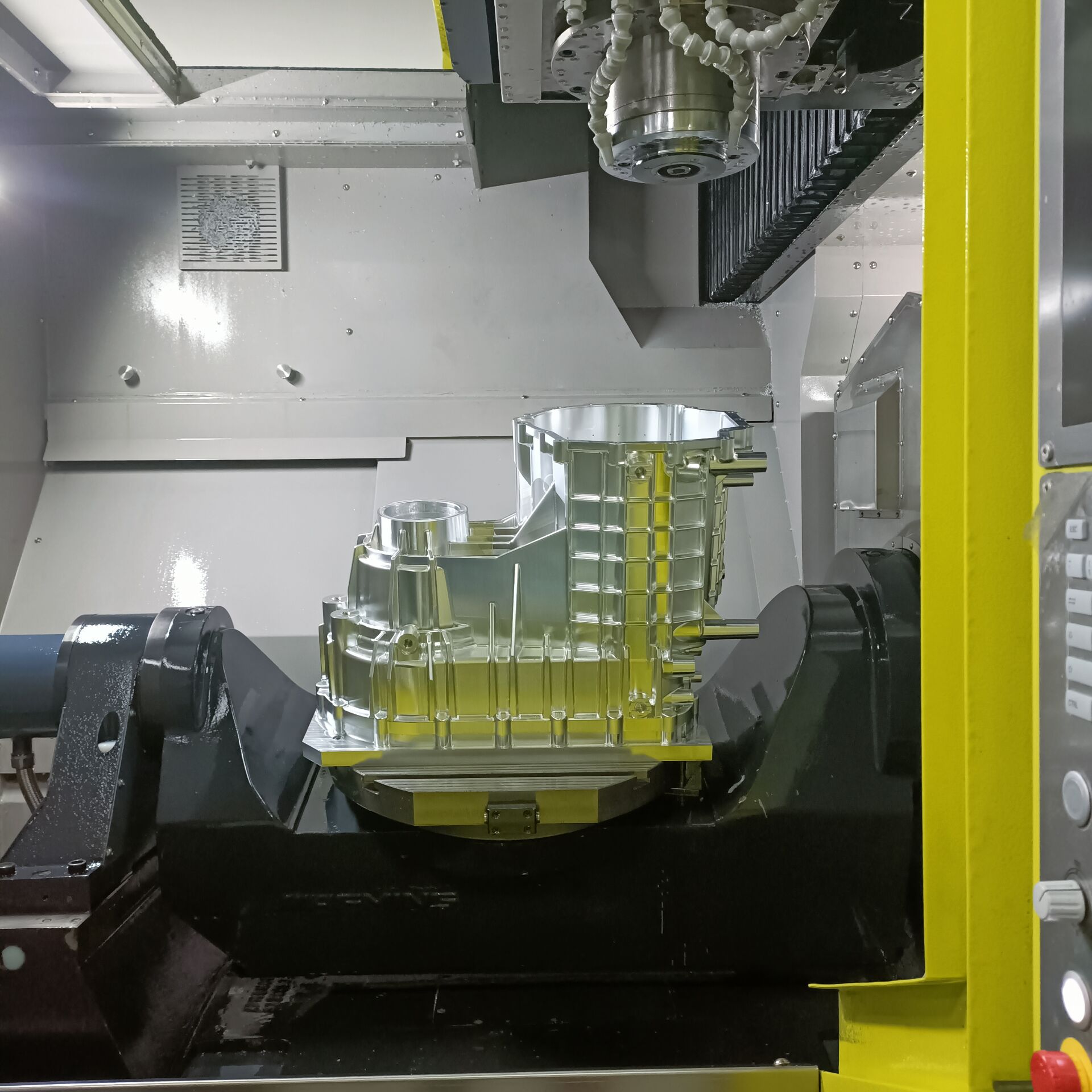
Gearbox Housing Manufacturing
KeSu has expertise machining gearboxes prototype constructed from standard and exotic metals with complex geometry to meet or exceed the most demanding tolerances.
Conclusion
Gearbox manufacturing is a complex process that demands careful material selection, advanced CNC machining techniques, and stringent precision control. By choosing appropriate materials like alloy steels, cast iron, or aluminum alloys, and employing processes such as hobbing, grinding, and precision milling, manufacturers can produce gears, shafts, and housings that meet the rigorous demands of modern applications. The detailed parameters and best practices outlined in this guide provide a roadmap for achieving high-quality gearbox components, ensuring reliability and performance in industries ranging from automotive to renewable energy.
Frequently Asked Questions (FAQ)
What materials are commonly used for gearbox components?
Gearbox components are typically made from alloy steels (e.g., AISI 4140, 4340), carburizing steels (e.g., 20MnCr5), stainless steels (e.g., 316, 17-4 PH), cast iron, and aluminum alloys (e.g., 6061-T6). The choice depends on factors like load, wear resistance, and environmental conditions.
What CNC machining processes are used for gears?
Gear machining involves blank preparation (turning), gear hobbing or milling for tooth profiles, heat treatment, and finish grinding. Parameters include cutting speeds of 60–100 m/min for hobbing and Ra 0.4–0.8 µm for tooth surface finish.
How are tight tolerances achieved in gearbox manufacturing?
Tight tolerances (e.g., ±0.005 mm for gear tooth profiles or shaft diameters) are achieved using multi-axis CNC machines, precision tooling, and in-process inspections with CMMs and gear measuring machines. Controlled environments and rigid fixturing also minimize errors.
Why is surface finish important in gearbox components?
Surface finish (e.g., Ra 0.4 µm for gear teeth or shaft bearing surfaces) reduces friction, wear, and noise while improving component longevity. CNC grinding and polishing processes are used to achieve these finishes consistently.