In mechanical machining, achieving geometric accuracy is critical for ensuring high-quality parts. The machining process involves a craft system comprising the workpiece, cutting tool, fixture, and machine tool. Deviations in geometric dimensions often arise due to initial errors in this system, categorized as static errors (related to the initial state of the system) and dynamic errors (related to the machining process). This article systematically outlines solutions to address geometric dimension deviations from four key aspects: workpiece, cutting tool, fixture, and machine tool. Each section provides detailed, experience-based technical strategies to enhance precision and ensure reliable outcomes.
Workpiece-Related Solutions
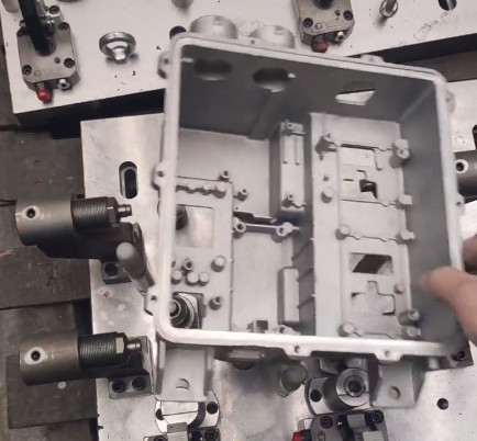
The workpiece is the core element of the mechanical machining process, and its preparation and handling significantly impact geometric accuracy. The following strategies address common issues related to workpiece setup, stress, and deformation.
Adhering to Machining Principles
Fundamental mechanical machining principles should guide the process to ensure dimensional accuracy. These include prioritizing datum surfaces before other features, machining surfaces before holes, focusing on primary features before secondary ones, and separating rough and finish machining. For instance, establishing a precise datum surface ensures subsequent operations align correctly, reducing cumulative errors.
Stress Release and Realignment
Before final finishing operations, loosening clamping plates to release residual stresses is essential. After realigning the workpiece, apply light clamping with a torque wrench to achieve optimal clamping force. Experimental validation is recommended to determine the ideal torque value, typically ranging from 10 to 20 Nm for small to medium-sized workpieces, ensuring both safety and quality.
Optimizing Clamping Points
Clamping forces must act on solid points to prevent deformation. If the clamping point is not solid, consider the following solutions:
- Multiple Clamping Steps: Split a single clamping operation into two stages, ensuring solid contact points. Realign the workpiece if necessary to maintain accuracy.
- Craft Bosses: Add temporary craft bosses to the workpiece for clamping. After mechanical machining, evaluate whether these bosses affect assembly and remove them if needed.
- Auxiliary Supports: Use hydraulic or mechanical machining supports at weak structural points. Modern hydraulic supports can achieve near-zero deformation, with contact forces typically below 5 kN for precision applications.
Ensuring Flatness of Positioning Surfaces
The flatness of the workpiece and fixture positioning surfaces is critical. Self-inspection of flatness, using tools like straightedges or dial indicators, should achieve a tolerance of 0.01–0.02 mm for precision parts. For large surfaces, replace solid fixture surfaces with adjustable pads to avoid warping. If flatness is poor, insert shims (e.g., copper foil or paper) to level the surface before clamping.
Thermal Management
Heat generated during machining can cause thermal deformation. Using cutting fluid with a flow rate of 5–10 L/min and a coolant temperature of 20–25°C helps dissipate heat, maintaining dimensional stability.
Stress Relief Through Aging
Perform aging treatments, such as natural or artificial aging, before semi-finishing to release internal stresses. For example, natural aging for 24–48 hours or thermal aging at 150–200°C for 2–4 hours can stabilize the workpiece material.
Specialized Clamping for Thin-Walled Parts
For thin-walled parts in turning, use soft jaws or split rings to minimize clamping stress. Alternatively, axial clamping (end-face pressure) can replace radial clamping, reducing deformation by up to 50% in some cases.
Counter-Deformation Machining
In turning operations, pre-machine the workpiece with an intentional counter-deformation to offset expected distortion. For example, if a part is expected to deflect by 0.05 mm, machine it with a -0.05 mm offset to achieve the desired final geometry.
Balancing Large Workpieces
For large, irregular workpieces, balance the center of mass by adding counterweights to reduce centrifugal forces during rotation. A dynamic balancing machine can ensure imbalance is kept below 5 g·mm/kg for high-speed operations.
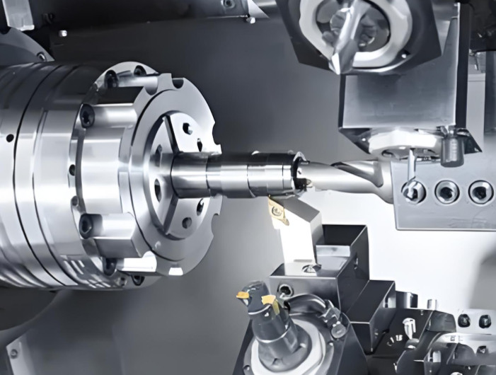
Cutting Tool-Related Solutions
Cutting tools directly influence mechanical machining accuracy through their condition, geometry, and interaction with the workpiece. The following measures ensure tool-related errors are minimized.
Preparing the Machining Surface
Before drilling, boring, or reaming, remove semi-walled structures or flatten rough surfaces to ensure uniform cutting forces. For example, spot-facing a rough surface to a flatness of 0.05 mm can reduce tool deflection by up to 30%.
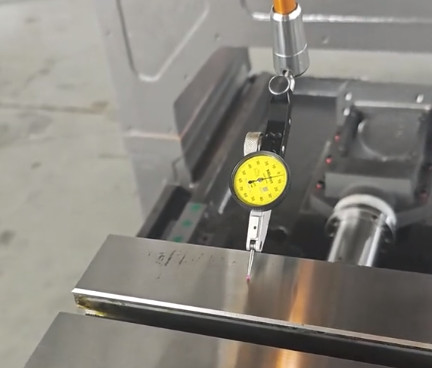
Tool Runout Inspection
Check radial and axial runout of tools before machining, adhering to standards like ISO 10889, which specifies runout tolerances of 0.01–0.02 mm for precision tools. Use a dial indicator or laser measurement system for verification.
Tool Handle Maintenance
Prevent damage to tool handles by avoiding impacts or scratches. Clean the machine spindle taper (e.g., BT40 or HSK63) weekly using specialized cleaning tools to maintain a taper contact accuracy of 0.002 mm.
Tool Geometry Optimization
Maintain sufficient tool diameter and minimize overhang length to enhance rigidity. For example, a tool overhang of less than 4 times the tool diameter is recommended for high-precision milling.
Dynamic Balancing for Precision
For high-precision workpieces, perform dynamic balancing of tools to ISO 1940-1 standards, achieving a balance quality grade of G2.5 or better at operating speeds (e.g., 10,000–20,000 RPM).
Cutting Parameter Adjustment
Optimize cutting parameters to minimize tool force, heat, and wear. For example, reduce cutting speed by 10–20% or adjust the rake angle by 2–5° to control chip formation and thermal effects.
Vibration-Resistant Tools
Use anti-vibration tools, such as those with internal damping mechanisms, to reduce chatter. These tools can decrease vibration amplitude by up to 40% in high-speed mechanical machining.
Fixture-Related Solutions
Fixtures ensure stable workpiece positioning and clamping, and their design directly affects machining accuracy. The following solutions address common fixture-related issues.
Improved Clamping Design
Avoid designs where clamping screws act on both the fixture and machine bed, as this can lift and deform the fixture. Ensure all clamping forces are applied within the fixture structure, maintaining deformation below 0.01 mm.
Fixture Rigidity
Design fixtures with sufficient stiffness, using materials like hardened steel or cast iron. The fixture’s deflection under maximum clamping force should not exceed 0.005 mm for precision applications.
Precision Mandrel Design
When using mandrels for positioning, grind the clamping threads to ensure perpendicularity between the thread axis and the positioning surface, achieving a tolerance of 0.01 mm.
Dynamic Balancing of Fixtures
For rotating fixtures in precision turning, perform dynamic balancing to maintain centrifugal deformation below 0.005 mm at operating speeds (e.g., 1,000–5,000 RPM).
Machine Tool-Related Solutions
The machine tool’s condition is critical for maintaining geometric accuracy. Regular inspection and maintenance are essential.
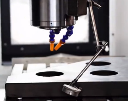
Accuracy Verification
Verify machine tool accuracy per standards like ISO 230-1. Check spindle-to-table perpendicularity (within 0.01 mm/300 mm) and spindle runout (within 0.005 mm). Use precision instruments like laser interferometers for measurements.
Maintenance Protocols
Implement a maintenance schedule to monitor critical components, such as spindle bearings and guideways, ensuring wear remains within 0.002–0.005 mm for high-precision machines.
Summary and Recommendations
Achieving geometric accuracy in mechanical machining requires a systematic approach addressing the workpiece, cutting tool, fixture, and machine tool. The following table summarizes key solutions and their technical specifications:
| Aspect | Solution | Technical Specification |
|---|---|---|
| Workpiece | Light Clamping | Torque: 10–20 Nm |
| Workpiece | Flatness Inspection | Tolerance: 0.01–0.02 mm |
| Cutting Tool | Runout Check | Tolerance: 0.01–0.02 mm |
| Fixture | Rigidity | Deflection: <0.005 mm |
| Machine Tool | Spindle Runout | Tolerance: <0.005 mm |
Additional recommendations include:
- Identify the specific cause of dimensional deviations (e.g., thermal, stress, or mechanical) before applying solutions.
- Use finite element analysis to predict craft system deformation and optimize process planning.
- Document and analyze solutions regularly to build a knowledge base for continuous improvement.
By implementing these strategies, manufacturers can achieve consistent geometric accuracy, enhancing product quality and reliability.