Guide vanes are critical components in turbomachinery, such as compressors, turbines, and pumps, where they direct fluid flow to optimize performance. This article provides a comprehensive overview of guide vanes, detailing their purpose, design principles, key parameters, and applications. By understanding their role, engineers can enhance system efficiency and reliability in various industrial contexts.
Understanding the Role of Guide Vanes
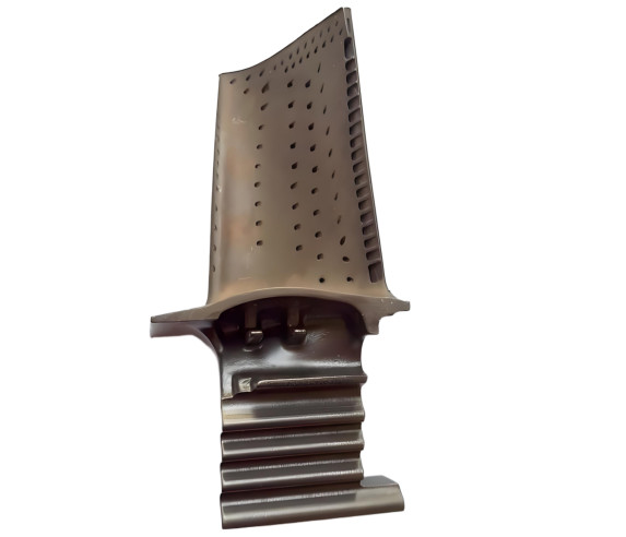
Guide vanes, also known as stator vanes or inlet guide vanes (IGVs), are stationary blades positioned within turbomachinery to direct fluid flow toward rotating components. Their primary function is to control the angle and velocity of the fluid entering or exiting a rotor, ensuring optimal aerodynamic performance. In compressors, guide vanes manage airflow to prevent stall and surge, while in turbines, they direct exhaust gases to maximize energy extraction.
The effectiveness of guide vanes lies in their ability to manipulate flow characteristics, such as velocity, pressure, and direction, to match the operational requirements of the machine. They are essential in maintaining stability across a range of operating conditions, from low to high flow rates, and contribute significantly to overall system efficiency.
Design Principles of Guide Vanes
The design of guide vanes is a complex process that requires balancing aerodynamic performance, structural integrity, and manufacturing constraints. Key considerations include vane geometry, material selection, and integration with other turbomachinery components.
Vane Geometry
The shape and orientation of guide vanes directly influence fluid dynamics. Parameters such as chord length, camber angle, and stagger angle are critical in determining flow behavior. For example, a typical inlet guide vane in a compressor may have a chord length of 50-100 mm, a camber angle of 20-40 degrees, and a stagger angle adjusted to align with the incoming flow. These parameters are optimized using computational fluid dynamics (CFD) to minimize losses and ensure uniform flow distribution.
Material Selection
Guide vanes are subjected to high mechanical and thermal stresses, particularly in gas turbines where temperatures can exceed 1000°C. Common materials include nickel-based superalloys for high-temperature applications and stainless steel or titanium alloys for compressors. Material properties, such as tensile strength (typically 800-1200 MPa for superalloys) and corrosion resistance, are critical to ensure durability.
Integration with Turbomachinery
Guide vanes must be precisely integrated with rotors and other stator components to maintain aerodynamic efficiency. Misalignment or improper spacing can lead to flow separation, reducing performance. For instance, the clearance between guide vanes and rotor blades is often maintained at 1-2% of the vane chord length to minimize turbulence.
Types of Guide Vanes
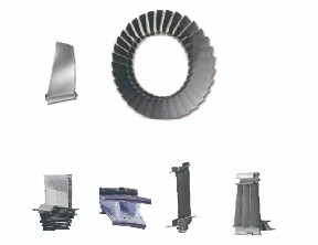
Guide vanes are classified based on their function and position within the turbomachinery. The two primary types are inlet guide vanes (IGVs) and stator vanes.
| Type | Function | Typical Application |
|---|---|---|
| Inlet Guide Vanes (IGVs) | Control airflow entering the compressor, adjusting angle to optimize performance | Gas turbines, axial compressors |
| Stator Vanes | Direct flow between rotor stages, maintaining pressure and velocity | Turbines, multistage compressors |
Inlet guide vanes are often adjustable, allowing real-time control of flow angles to adapt to varying operating conditions. Stator vanes, on the other hand, are typically fixed and designed to maintain consistent flow characteristics across multiple stages.
Performance Impact of Guide Vanes
Guide vanes significantly influence the efficiency, stability, and operational range of turbomachinery. Their performance can be quantified through parameters such as pressure ratio, flow coefficient, and efficiency.
Pressure Ratio
The pressure ratio, defined as the ratio of outlet to inlet pressure, is a key metric in compressors. Well-designed guide vanes can increase the pressure ratio by 1.2-1.5 per stage in axial compressors, depending on the vane design and flow conditions.
Flow Coefficient
The flow coefficient, a dimensionless parameter, measures the ratio of axial flow velocity to rotor tip speed. Guide vanes help maintain an optimal flow coefficient (typically 0.4-0.6) to prevent stall and ensure efficient energy transfer.
Efficiency
Efficiency is a measure of how effectively the turbomachinery converts input energy into useful work. Guide vanes contribute to efficiency by reducing aerodynamic losses, such as those caused by flow separation or turbulence. For example, optimized guide vanes can improve compressor efficiency by 2-5% in high-performance systems.
Applications of Guide Vanes
Guide vanes are used in a wide range of industries, including aerospace, power generation, and industrial processing. Their specific applications depend on the type of turbomachinery and operational requirements.
Aerospace
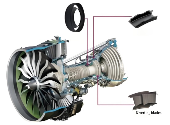
In jet engines, inlet guide vanes control airflow into the compressor, ensuring stable operation across a range of flight conditions. For example, in a turbofan engine, IGVs adjust the flow angle to maintain a pressure ratio of 1.3-1.6 per stage, enabling efficient thrust generation.
Power Generation
In gas and steam turbines, stator vanes direct hot gases to maximize energy extraction. For instance, in a gas turbine, guide vanes are designed to handle gas temperatures up to 1500°C, with cooling mechanisms such as internal air channels to maintain structural integrity.
Industrial Pumps
In centrifugal pumps, guide vanes (often called diffuser vanes) convert kinetic energy into pressure, improving pump efficiency. Typical diffuser vanes have a divergence angle of 8-12 degrees to minimize flow separation.
Key Parameters and Specifications
The performance of guide vanes depends on precise engineering of their geometric and operational parameters. The following table summarizes typical specifications for guide vanes in a compressor:
| Parameter | Typical Value | Description |
|---|---|---|
| Chord Length | 50-100 mm | Length of the vane along its surface |
| Camber Angle | 20-40 degrees | Curvature of the vane surface |
| Stagger Angle | 10-30 degrees | Angle of vane orientation relative to flow |
| Material | Nickel-based superalloy | High-strength, heat-resistant material |
| Clearance | 1-2% of chord length | Gap between vane and rotor |
These parameters are tailored to specific applications, with adjustments made based on CFD simulations and experimental testing to optimize performance.
Manufacturing and Maintenance Considerations
The production and upkeep of guide vanes require precision engineering and regular maintenance to ensure long-term performance.
Manufacturing Techniques
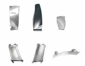
Guide vanes are typically manufactured using precision casting, forging, or additive manufacturing (3D printing) for complex geometries. For example, investment casting is used for turbine stator vanes to achieve tolerances of ±0.1 mm, ensuring aerodynamic accuracy.
Maintenance Practices
Regular inspection of guide vanes is critical to detect wear, erosion, or thermal damage. Non-destructive testing methods, such as ultrasonic or X-ray inspection, are used to assess structural integrity. In high-temperature environments, vanes may require periodic coating with thermal barrier materials to extend service life.
FAQ
What is the primary function of guide vanes?
Guide vanes direct fluid flow in turbomachinery to optimize aerodynamic performance, control flow angles, and enhance efficiency.
How do inlet guide vanes differ from stator vanes?
Inlet guide vanes are adjustable and control flow entering the compressor, while stator vanes are fixed and direct flow between rotor stages.
What materials are used for guide vanes?
Common materials include nickel-based superalloys for turbines and stainless steel or titanium alloys for compressors, chosen for strength and heat resistance.