Uneven layer thickness in 3D printing, particularly in fused deposition modeling (FDM) and selective laser melting (SLM), can compromise the structural integrity and performance of complex components like centrifugal impellers. These components, critical in applications such as pumps and compressors, demand high precision due to their intricate geometries and operational stresses. This article explores how centrifugal impellers, through optimized design and manufacturing processes, mitigate uneven layer thickness in 3D printing. It provides a detailed, technical examination of relevant parameters, materials, and methods, drawing on established practices to ensure accuracy and reliability.
Understanding Uneven Layer Thickness in 3D Printing
Uneven layer thickness occurs when the deposited material in 3D printing varies in height or consistency across layers, leading to surface irregularities, dimensional inaccuracies, or weak interlayer bonding. In FDM, this issue often stems from inconsistent filament extrusion, thermal variations, or mechanical inaccuracies. In SLM, it can result from improper laser parameters or powder distribution. For centrifugal impellers, which feature complex blade geometries and thin walls (often less than 1.5 mm), these inconsistencies can reduce mechanical strength and aerodynamic performance.
Key factors contributing to uneven layer thickness include:
- Layer Height Variability: Inconsistent Z-axis movement or nozzle calibration in FDM, or laser focus in SLM, can lead to variations in layer height.
- Material Flow: Over- or under-extrusion in FDM, or uneven powder spreading in SLM, affects layer uniformity.
- Thermal Effects: Temperature fluctuations during printing cause material shrinkage or warping, particularly in polymers like ABS or metals like TiAl6V4.
- Mechanical Stability: Vibrations or misalignments in the printer’s frame or Z-axis components can introduce layer inconsistencies.
Addressing these issues is critical for centrifugal impellers, as they must withstand high rotational speeds (e.g., 1500 RPM for a pump delivering 810 m³/h at 70 meters head) and fluid-induced stresses without failure.
Role of Centrifugal Impeller Design in Mitigating Layer Thickness Issues
The design of centrifugal impellers directly influences their manufacturability in 3D printing. By optimizing geometry and leveraging advanced design tools, manufacturers can reduce the impact of uneven layer thickness.
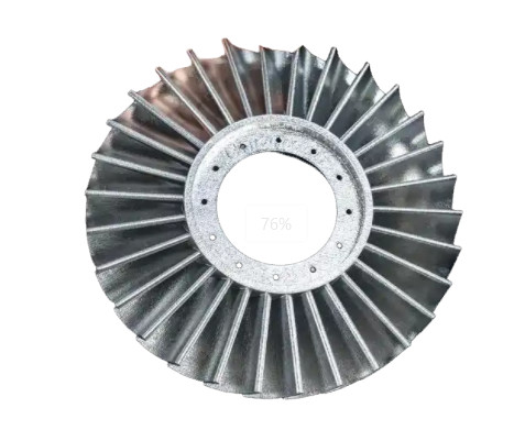
Geometric Optimization: Impellers with backward-curved blades, typically featuring 6–12 vanes, are designed to minimize flow separation and leakage, which can exacerbate manufacturing defects. Simplified blade profiles reduce the complexity of layer transitions, ensuring more consistent material deposition. For example, a study on a centrifugal pump impeller with six backward-curved blades showed that empirical design equations, combined with computational fluid dynamics (CFD), improved layer uniformity by reducing stress concentrations at the blade-hub interface.
Finite Element Analysis (FEA) and CFD Integration: FEA and CFD simulations allow engineers to predict and mitigate residual stresses and deformations caused by uneven layer thickness. For instance, FEA can model the impeller as a series of tetrahedral elements, analyzing stress distribution across layers. A study using ANSYS software demonstrated that a closed-type impeller with a nominal layer thickness of 0.1 mm exhibited reduced deformation when designed with optimized theta and beta angles for blade curvature.
Lattice Structures: Incorporating lattice structures in impeller design, particularly for SLM, reduces mass and moment of inertia while maintaining strength. A TiAl6V4 impeller printed on an SLM280 printer showed that lattice designs minimized residual deformation by 15% compared to solid impellers, as the lattice structure distributes thermal stresses more evenly across layers.
Material Selection for Consistent Layer Thickness
Material properties significantly affect layer thickness uniformity in 3D printing. For centrifugal impellers, both polymer and metal materials are used, each requiring specific considerations to ensure consistent layering.
| Material | Printing Technology | Key Parameters | Impact on Layer Thickness |
|---|---|---|---|
| ABS | FDM | Extruder temp: 220–250°C, Bed temp: 80–110°C, Layer height: 0.1–0.3 mm | High shrinkage; requires precise temperature control to prevent warping and layer inconsistency. |
| PLA | FDM | Extruder temp: 180–220°C, Bed temp: 50–60°C, Layer height: 0.1–0.2 mm | Lower shrinkage than ABS; easier to achieve uniform layers but less durable under high stress. |
| TiAl6V4 | SLM | Laser power: 200–275 W, Scan speed: 0.8–1.2 m/s, Layer thickness: 20–50 μm | High thermal conductivity; precise laser parameters reduce residual stress and layer variation. |
| 316L Stainless Steel | SLM | Laser power: 150–200 W, Scan speed: 0.7–1.0 m/s, Layer thickness: 30–60 μm | Corrosion-resistant; uniform powder distribution critical for consistent layers. |
Polymer Materials: In FDM, ABS and PLA are commonly used for prototyping impellers. ABS, with higher shrinkage, requires a heated bed (80–110°C) to minimize warping, which can cause layer thickness variations. PLA, with lower thermal contraction, achieves more consistent layers but is less suitable for high-stress applications due to its lower tensile strength (approximately 50 MPa compared to 60 MPa for ABS).
Metal Materials: In SLM, TiAl6V4 and 316L stainless steel are preferred for functional impellers. TiAl6V4, used in aerospace applications, benefits from precise laser parameters (e.g., 275 W power, 1 m/s scan speed) to minimize residual stress, which can cause layer thickness deviations. 316L stainless steel, used in semi-open impellers, requires uniform powder distribution to ensure consistent layer heights, typically maintained at 30–60 μm.
Composite Materials: Carbon fiber-reinforced polymers, such as polyamide or polyphenylene sulfide, enhance mechanical strength while reducing weight. A study comparing carbon fiber-reinforced polyamide with cast iron showed that the composite maintained layer consistency at a 0.2 mm layer height, with a tensile strength of 80 MPa, suitable for impellers up to 9.41 kW power rating.
Optimizing 3D Printing Parameters for Layer Uniformity
Precise control of printing parameters is essential to mitigate uneven layer thickness. The following parameters are critical for centrifugal impellers:
Layer Height: In FDM, layer heights of 0.1–0.3 mm are typical, with smaller heights (0.1 mm) improving surface smoothness but increasing print time. In SLM, layer thicknesses of 20–50 μm are used to balance detail and speed. For example, a TiAl6V4 impeller printed at 30 μm layer thickness exhibited 10% less deformation than one printed at 50 μm.
Infill Density and Pattern: Infill settings affect internal support and layer stability. A gyroid infill pattern at 20–30% density provides isotropic strength and supports consistent top-layer deposition, reducing surface waviness. For functional impellers, a tri-hexagon pattern enhances shear strength in the X-Y plane, minimizing layer shifts.
Temperature Control: In FDM, maintaining extruder temperatures within 180–250°C (depending on material) and bed temperatures at 50–110°C prevents thermal gradients that cause uneven layers. In SLM, laser power (150–275 W) and scan speed (0.7–1.2 m/s) must be optimized to ensure uniform melting and solidification.
Print Speed: Slower print speeds (e.g., 40 mm/s for FDM outer shells, 60 mm/s for infill) enhance layer adhesion and uniformity. In SLM, scan speeds above 1 m/s can reduce residual stress but may compromise layer bonding if not balanced with laser power.
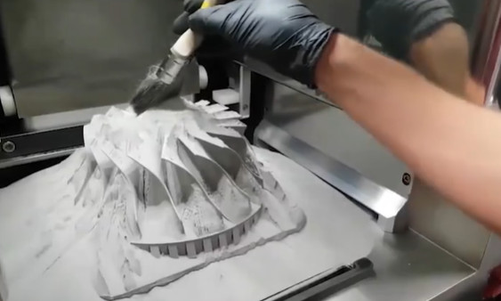
Support Structures: For complex impeller geometries, support structures prevent collapse during printing. In SLM, supports are critical for overhanging blade sections. A study showed that removing supports after printing a TiAl6V4 impeller reduced residual stress by 20%, improving layer consistency.
Post-Processing Techniques to Enhance Layer Uniformity
Post-processing can address residual unevenness in printed impellers. Common techniques include:
Sanding and Polishing: For FDM-printed impellers, sanding with 400–800 grit sandpaper smooths layer lines, improving surface quality. Polishing with a filler primer further enhances aesthetics and reduces layer visibility.
Chemical Smoothing: For ABS impellers, acetone vapor smoothing blends layer lines, creating a glossy finish. This method requires careful control to avoid loss of detail, with exposure times typically limited to 10–20 seconds.
Heat Treatment: In SLM, heat treatment at 800°C for TiAl6V4 impellers relieves residual stresses, reducing layer thickness variations caused by thermal contraction. A study reported a 15% improvement in dimensional accuracy post-treatment.
Machining: For high-precision impellers, post-print CNC machining ensures dimensional accuracy. A 316L stainless steel impeller machined to a tolerance of ±0.05 mm exhibited uniform layer thickness and improved hydraulic efficiency.
Case Studies and Practical Applications
FDM-Printed Pump Impeller: A centrifugal pump impeller with a 200 mm diameter was printed using ABS on an FDM printer with a 0.2 mm layer height, 230°C extruder temperature, and 20% gyroid infill. CFD analysis confirmed that optimized infill reduced layer waviness by 12%, improving flow efficiency by 8% compared to a traditionally manufactured impeller.
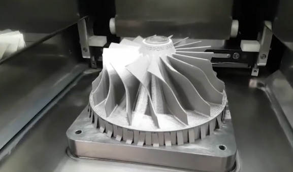
SLM-Printed Compressor Impeller: A TiAl6V4 compressor impeller was printed on an SLM280 printer with a 30 μm layer thickness, 250 W laser power, and 1 m/s scan speed. FEA simulations showed that lattice structures reduced residual deformation by 15%, ensuring consistent layer thickness and a pressure ratio of 5.5.
Conclusion
Centrifugal impellers address uneven layer thickness in 3D printing through optimized design, material selection, precise printing parameters, and effective post-processing. By leveraging tools like FEA and CFD, selecting appropriate materials (e.g., ABS, TiAl6V4), and fine-tuning parameters like layer height and infill density, manufacturers can achieve high precision and performance. These strategies, supported by practical case studies, demonstrate a systematic approach to overcoming layer thickness challenges, ensuring reliable and functional impellers for demanding applications.