Impeller machining is a critical process in industries such as aerospace, automotive, and energy, where precision is essential. Achieving a true profile error of 0.007mm demands advanced equipment, meticulous process control, and rigorous quality assurance. This guide provides a systematic approach to controlling impeller machining errors, leveraging established techniques and precise parameters to ensure high accuracy and reliability.
Understanding True Profile Error in Impeller Machining
True profile error refers to the deviation between the machined impeller surface and the theoretical design profile, measured in millimeters. For impellers with complex geometries, such as twisted blades and free-form surfaces, maintaining a profile error within 0.007mm is challenging due to material properties, tool deflection, and machine dynamics. The objective is to minimize deviations to ensure aerodynamic efficiency, structural integrity, and operational reliability.
Key factors include material selection, machining strategy, and inspection methods. Impellers are typically made from materials like aluminum alloys, titanium (e.g., TC4), or stainless steel, each with unique machining characteristics. The process must account for these properties while utilizing advanced CNC technology to achieve the desired precision.
Material Selection and Preparation
Material choice significantly impacts machining accuracy. Forged aluminum alloy (e.g., 6061-T651) is often selected for its lightweight properties, high strength, and corrosion resistance, making it ideal for aerospace impellers. Titanium alloys, such as TC4, are used for their durability but pose challenges due to low thermal conductivity and high hardness.
Before machining, thorough material inspection ensures defect-free blanks. The following steps are recommended:
- Chemical Composition Analysis: Use an XRF analyzer (e.g., Olympus Vanta Element-S) to verify compliance with standards like ASTM B247 for aluminum alloys.
- Mechanical Property Testing: Conduct tensile and hardness tests to confirm material strength and consistency.
- Non-Destructive Testing (NDT): Employ ultrasonic or X-ray inspection to detect internal defects, ensuring the blank is free of voids or inclusions.
Proper material preparation reduces the risk of machining errors caused by inconsistencies, providing a stable foundation for achieving the 0.007mm profile tolerance.
Advanced Machining Equipment and Setup
Five-axis CNC machining centers are critical for precision impeller manufacturing due to their ability to handle complex geometries. A machine like the GROB 350, with a travel range of 600x855x750mm and positional accuracy of 0.002mm, is well-suited for impeller machining. Key equipment specifications include:
| Parameter | Specification |
|---|---|
| Machine Type | 5-Axis CNC Machining Center |
| Travel Range | 600x855x750mm |
| Positional Accuracy | 0.002mm |
| Spindle Speed | Up to 24,000 RPM |
Machine Setup:
- Fixture Design: Use specialized fixtures to ensure clamping rigidity, minimizing vibration and workpiece movement. Hydraulic or vacuum fixtures are preferred for complex impeller shapes.
- Tool Selection: Choose high-precision tools, such as carbide end mills or ball mills, with diameters tailored to the impeller’s geometry (e.g., 6mm for narrow channels, 12mm for roughing).
- Spindle Calibration: Ensure the spindle is calibrated to maintain thermal stability, as even 4-5 microns of thermal expansion can affect precision.
Environmental control is vital. Maintain a stable machining environment with temperature control (e.g., 20±1°C) and vibration isolation using active air pads to prevent external disturbances, such as those from nearby equipment like forklifts.
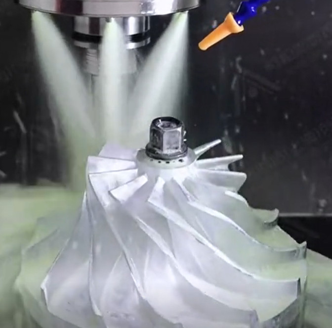
Machining Process Optimization
The machining process for impellers typically involves multiple stages: roughing, semi-finishing, and finishing. Each stage requires specific strategies to minimize profile errors.
Rough Machining:
- Use a large-travel CNC lathe to remove bulk material efficiently.
- Maintain a conservative depth of cut (e.g., 1-2mm) to reduce tool deflection and heat generation.
- Monitor cutting forces to avoid excessive stress on the workpiece.
Semi-Finishing:
- Employ a 5-axis machining center to shape blades and hubs, using NURBS-based toolpaths for smooth transitions.
- Implement adaptive machining strategies to adjust feed rates based on real-time feedback from in-process measurement systems.
- Use a feed rate of 0.05-0.1mm/tooth for aluminum alloys to balance efficiency and precision.
Finishing:
- Utilize high-speed machining with spindle speeds of 18,000-24,000 RPM to achieve fine surface finishes.
- Apply a step-over of 0.02-0.03mm for ball-end mills to ensure smooth surface transitions.
- Use coolant with a flow rate of 20-30 L/min to minimize thermal distortion and tool wear.
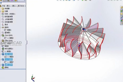
Toolpath optimization is critical. CAM software like Siemens NX or Mastercam can generate 5-axis toolpaths that minimize cutter deflection and ensure uniform material removal. Adaptive feed rate control, based on cutting load, helps maintain consistent machining conditions.
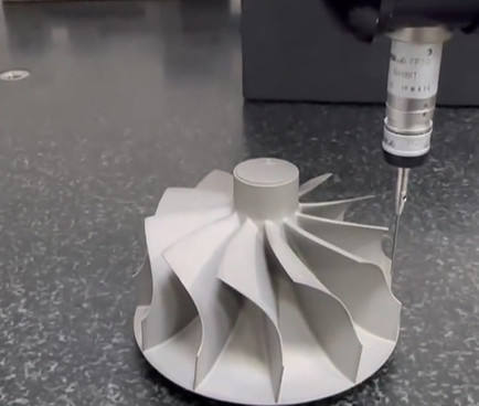
Quality Control and Inspection
Achieving a 0.007mm true profile error requires rigorous inspection at every stage. Coordinate Measuring Machines (CMMs), such as the Zeiss ACCURA, with a measurement accuracy of 0.001mm, are ideal for verifying impeller geometry. Inspection protocols include:
- In-Process Inspection: Use on-machine probing systems (e.g., Renishaw OMP60) to measure critical features during machining, allowing real-time adjustments.
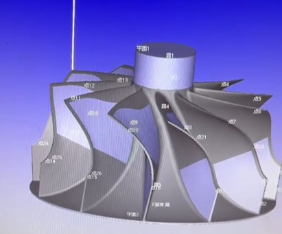
- Final Inspection: Perform a full 3D scan using a CMM or laser scanner (e.g., FARO Quantum S) to compare the machined impeller against the CAD model.
- Profile Tolerance Verification: Analyze scan data with software like Geomagic Control X to quantify profile deviations, ensuring they are within 0.007mm.
Statistical Process Control (SPC) is recommended to monitor machining consistency. Track key metrics like tool wear and surface roughness (Ra < 0.4μm) to identify deviations early.
| Inspection Method | Equipment | Accuracy |
|---|---|---|
| CMM | Zeiss ACCURA | 0.001mm |
| Laser Scanning | FARO Quantum S | 0.025mm |
| On-Machine Probing | Renishaw OMP60 | 0.002mm |
Process Stability and Operator Training
Process stability is crucial for maintaining tight tolerances. Regular machine maintenance, including spindle and axis calibration, ensures consistent performance. Operators must be trained in advanced CNC programming, toolpath optimization, and quality control techniques.
Training programs should cover:
- Programming 5-axis toolpaths using CAM software.
- Interpreting CMM reports and adjusting machining parameters.
- Monitoring tool wear and replacing tools at predefined intervals (e.g., after 120 minutes of cutting time for titanium alloys).
Experienced operators can identify subtle issues, such as vibration patterns or coolant inconsistencies, that automated systems may miss, further ensuring precision.
Post-Machining Processes
After machining, additional processes like surface treatment or polishing may be required to meet the 0.007mm profile tolerance. For instance, vibratory finishing can achieve a surface roughness of Ra 0.2μm, enhancing aerodynamic performance. However, care must be taken to avoid altering critical dimensions during these processes.
Final verification using a CMM ensures that post-machining treatments do not compromise the profile tolerance. If deviations are detected, localized rework using hand-finishing techniques or additional CNC passes may be necessary.
Conclusion
Controlling impeller machining true profile error to 0.007mm requires a systematic approach encompassing material preparation, advanced equipment, optimized machining processes, rigorous quality control, and skilled operators. By carefully selecting materials, leveraging 5-axis CNC technology, optimizing toolpaths, and implementing robust inspection protocols, manufacturers can achieve the required precision. Consistent environmental control and operator expertise further enhance reliability, ensuring impellers meet stringent performance and durability requirements.