Aluminum-magnesium alloys are widely used in engine casing manufacturing due to their corrosion resistance and high specific strength. However, their low hardness results in significant internal thread damage in threaded connections. To address this, thread inserts are employed to protect internal threads. Key-locked thread inserts, an advanced type of fastener developed in recent years, incorporate a locking mechanism to enhance anti-loosening properties. These inserts significantly improve the reliability and service life of threaded connections in engine casings. This article provides a comprehensive analysis of the structure, material selection, processing techniques, installation procedures, and maintenance methods for key-locked thread inserts, emphasizing their technical significance in aluminum-magnesium alloy applications.
Structural Characteristics of Key-Locked Thread Inserts
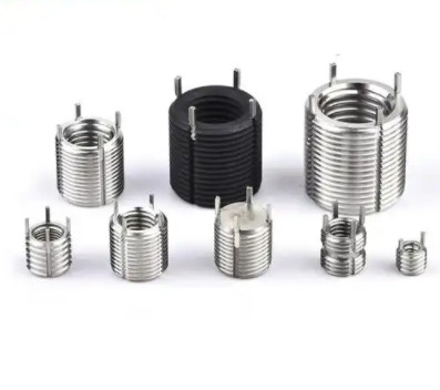
Key-locked thread inserts consist of two main components: the thread insert body and locking keys. The insert body includes internal and external threads and a keyway zone for key installation. The external threads connect the insert to the base material, while the internal threads engage with bolts, screws, or studs. The locking keys, comprising a key tongue and a key handle, are pre-installed in the keyway. The key handle, designed in a "V" shape to accommodate thread debris during plastic deformation, facilitates installation by hammering the keys into the base material, creating interference with the internal threads to secure the insert.
Key-locked thread inserts are categorized into two types based on the locking position:
- Middle-Locked Type: The locking keys are positioned in the middle of the insert, providing balanced locking force.
- End-Locked Type: The locking keys are located at the end of the insert, suitable for specific structural requirements.
The internal threads form a self-locking thread pair with the mating fastener, where plastic deformation at the thread closure creates interference friction, enhancing anti-loosening performance. Thread specifications include American (Unified) and MJ threads, with external thread tolerances of 2A, 5h6h, or 4h6h, and internal thread tolerances of 3B or 4H5H. These threads feature an enlarged root radius to improve fatigue strength, making them ideal for aerospace applications.

Material Selection and Treatment
Key-locked thread inserts are manufactured from high-performance materials to meet demanding operational conditions. The primary materials used are:
| Material | Properties | Applications |
|---|---|---|
| High-Temperature Alloy (A286/YZGH2132) | Excellent oxidation resistance, high-temperature strength (600–1200°C), and fatigue resistance | High-temperature aerospace components |
| 17-4PH Martensitic Stainless Steel | High strength, good plasticity, toughness, and corrosion resistance to weak acids, alkalis, and salts | Aerospace components requiring durability and corrosion resistance |
Post-processing includes heat treatment to achieve a hardness of 36–42 HRC, enhancing mechanical properties. Surface treatment involves passivation and coating with molybdenum disulfide (MoS2) dry film lubricant. Passivation improves corrosion resistance, while MoS2 reduces friction during installation, minimizing the risk of thread galling.
Technical Specifications
Key-locked thread inserts are evaluated based on six technical metrics:
- Locking Performance: Assesses the insert’s ability to prevent loosening after repeated use.
- Torque Resistance Test: Measures the insert’s resistance to rotational forces.
- Pull-Out Test: Evaluates the insert’s resistance to axial extraction from the base material.
- Tensile Test: Verifies the insert’s axial load-bearing capacity without fracture or damage.
- Hardness: Ensures the material meets the specified hardness range (36–42 HRC).
- Metallurgical Properties: Inspects for defects such as cracks, folds, or thread imperfections.
These metrics ensure the inserts meet stringent performance requirements for aerospace and engine applications.
Processing Techniques
The manufacturing of key-locked thread inserts involves precise processes to ensure quality and performance:
External Thread Processing
The external threads are formed through thread rolling, a cold-forming process that enhances thread strength by creating continuous metal flow lines. This method improves tensile load capacity and fatigue life while maintaining high thread accuracy and surface finish. The rolling process ensures compliance with tolerances such as 2A, 5h6h, or 4h6h.
Internal Thread Processing
Internal threads are machined using specialized taps with titanium aluminum nitride (TiAlN) coatings. Dedicated fixtures ensure coaxiality between internal and external threads, maintaining dimensional accuracy and surface quality. The use of coated taps reduces wear and improves thread consistency.
Keyway Processing
The keyway is machined using wire electrical discharge machining (WEDM) with a 0.2 mm molybdenum wire in a slow-feed process. This minimizes surface burning caused by electrical discharge. Post-WEDM, a specialized tool removes the burn layer to achieve the required surface roughness, ensuring proper key installation.
Installation Process
The installation of key-locked thread inserts involves precise preparation and execution to ensure secure integration with the base material. The process includes:
- Base Hole Preparation: Drill a base hole according to the thread specification and base material properties. The hole depth must accommodate the effective thread length.
- Counterboring: Use a counterbore drill to create a flat seating surface for the insert.
- Thread Tapping: Tap the base hole with a spiral flute or thread-forming tap matching the insert’s external thread specification.
- Insert Installation: Use a dedicated installation tool to screw the insert into the tapped hole.
- Key Installation: Hammer the locking keys into the base material, ensuring interference with the internal threads.
- Tool Removal: Remove the installation tool to complete the process.
Proper hole preparation and tool selection are critical to achieving a secure fit and preventing damage to the base material.

Maintenance and Repair
Key-locked thread inserts may require replacement due to thread wear from repeated use or installation failures. The removal and replacement process is as follows:
- Material Removal: Drill out the material between the locking keys to release the insert.
- Key Extraction: Bend and remove the locking keys carefully to avoid damaging the base material.
- Insert Removal: Extract the remaining insert material without harming the base material’s threads.
- Replacement: Install a new insert of the same specification into the original hole.
Specialized removal tools ensure the base material’s threads remain intact, allowing for repeated repairs without compromising structural integrity.
Conclusion
Key-locked thread inserts offer a robust solution for enhancing the strength and anti-loosening performance of threaded connections in aluminum-magnesium alloy engine casings. Their unique structure, combining a locking mechanism with high-performance materials, ensures reliable operation under demanding conditions. The precise processing techniques, including thread rolling, tapping, and wire EDM, guarantee high quality and durability. The standardized installation and maintenance procedures simplify integration and repair, making these inserts an efficient and cost-effective choice for aerospace applications. By replacing traditional lock washers and nuts, key-locked thread inserts streamline assembly, improve reliability, and extend the service life of critical components.