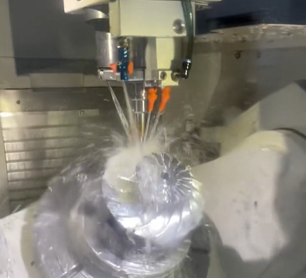
Five-axis machining centers are essential for manufacturing turbine impellers, which feature complex geometries and require high precision. These advanced CNC systems enable efficient and accurate machining of intricate surfaces, such as those found in turbine impellers used in aerospace, automotive, and energy industries. This article provides a comprehensive guide on how to optimize the machining process for turbine impeller complex surfaces, detailing the technical processes, parameters, and practical applications that ensure high efficiency and precision.
Understanding Turbine Impeller Geometry and Machining Requirements
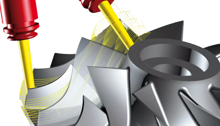
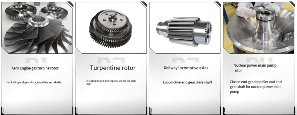
Turbine impellers, such as those used in jet engines or turbochargers, are characterized by complex, freeform surfaces, including twisted blades, thin walls, and intricate flow channels. These components operate under extreme conditions, necessitating exceptional surface finish, dimensional accuracy, and material integrity. The primary machining requirements include:
- Complex Surface Geometry: Impellers feature non-linear, curved surfaces that require multi-angle tool access.
- 높은 정밀도: Tolerances are typically within ±0.01 mm to ensure aerodynamic performance and structural integrity.
- Material Challenges: Impellers are often made from difficult-to-machine materials like 티타늄 합금, Inconel, or aluminum, requiring robust cutting strategies.
- 효율성: Single-setup machining is preferred to minimize repositioning errors and reduce production time.
Five-axis machining centers address these requirements by providing simultaneous control over five axes (X, Y, Z, A, C), enabling dynamic tool positioning and continuous surface machining without repositioning the workpiece.
Key Mechanisms of Five-Axis Machining Centers
Five-axis machining centers differ from traditional three-axis systems by incorporating two additional rotational axes (typically A and C). This allows the cutting tool to approach the workpiece from virtually any angle, optimizing the machining of complex surfaces. The key mechanisms include:
- Simultaneous Five-Axis Motion: The X, Y, and Z linear axes, combined with A (rotation around X-axis) and C (rotation around Z-axis), enable continuous toolpath adjustments to match the impeller’s geometry.
- High-Precision Spindles: Spindles with speeds ranging from 12,000 to 24,000 RPM ensure efficient material removal and fine surface finishes.
- Advanced Control Systems: CNC systems like FANUC or Siemens integrate real-time error compensation and adaptive control to maintain accuracy.
- Toolpath Optimization Software: Software such as hyperMILL or VERICUT generates collision-free toolpaths tailored to impeller geometries.
These mechanisms allow five-axis machining centers to handle the intricate contours of turbine impellers while maintaining tight tolerances and minimizing machining time.
Toolpath Planning and Optimization for Impeller Machining
Effective toolpath planning is critical for optimizing impeller machining. Five-axis machining centers leverage advanced CAM software to generate precise toolpaths that account for the impeller’s complex geometry. The process involves:
- Roughing: Initial material removal using high-feed milling tools, typically with a feed rate of 1,000–2,000 mm/min and a depth of cut of 0.5–2 mm.
- Semi-Finishing: Refining the surface with smaller stepovers (0.1–0.3 mm) to prepare for final finishing.
- Finishing: Achieving surface roughness values of Ra 0.8–1.6 µm using ball-end mills or toroidal cutters with diameters of 6–12 mm.
Key optimization strategies include:
- Adaptive Toolpaths: CAM software adjusts toolpaths to maintain consistent chip thickness (e.g., 0.05–0.15 mm/tooth), reducing tool wear and improving surface quality.
- Collision Avoidance: Five-axis systems use real-time simulation to prevent tool-workpiece or tool-fixture collisions, critical for narrow impeller channels.
- Constant Cutting Conditions: Maintaining stable spindle loads (e.g., 60–80% of maximum) by adjusting feed rates and cutting depths dynamically.
Software like hyperMILL supports these strategies by integrating algorithms such as genetic algorithms or particle swarm optimization to fine-tune toolpaths, ensuring efficient material removal and minimal machining time.
Fixture Design and Workpiece Stability
Impeller machining requires robust fixturing to prevent deformation, especially for thin-walled blades. Five-axis machining centers reduce fixture dependency compared to three-axis systems, but optimized fixture design remains critical. Key considerations include:
- Minimal Clamping Points: Using three-jaw or four-jaw chucks for regular geometries or one-face-two-pin setups for irregular shapes to minimize setup time.
- Vibration Control: High-stiffness fixtures reduce chatter, ensuring surface finish quality (Ra < 1.6 µm).
- Accessibility: Open fixture designs allow tool access to all impeller surfaces, leveraging the five-axis system’s flexibility.
For example, a typical impeller fixture might use a modular zero-point clamping system, reducing setup time by 30–50% compared to traditional fixtures. In-process measurement technologies, such as laser probes, further enhance accuracy by quantifying deformation and adjusting machining parameters in real time.
Machining Parameters for Turbine Impellers
Optimizing machining parameters is essential for achieving high-quality impeller surfaces. The following table outlines typical parameters for machining titanium alloy impellers using a five-axis CNC machining center:
| Operation | 도구 유형 | Spindle Speed (RPM) | Feed Rate (mm/min) | 컷 깊이(mm) | Surface Roughness (Ra, µm) |
|---|---|---|---|---|---|
| 러프닝 | High-feed mill (Ø20 mm) | 12,000–15,000 | 1,500–2,000 | 1.0–2.0 | 3.2–6.3 |
| 반가공 | Ball-end mill (Ø10 mm) | 15,000–18,000 | 800–1,200 | 0.2–0.5 | 1.6–3.2 |
| 마무리 | Toroidal cutter (Ø8 mm) | 18,000–24,000 | 500–800 | 0.05–0.1 | 0.8–1.6 |
These parameters are adjusted based on material properties. For titanium alloys, lower feed rates and depths of cut are used to manage heat generation, while aluminum alloys allow higher speeds and feeds. Coolant strategies, such as high-pressure through-spindle coolant (70–100 bar), further enhance tool life and surface quality.
Material-Specific Considerations
Turbine impellers are often made from materials with unique machining characteristics. Five-axis machining centers must adapt to these properties to optimize performance. Key material-specific considerations include:
- Titanium Alloys (e.g., Ti-6Al-4V): Low thermal conductivity requires low cutting speeds (50–80 m/min) and high-pressure coolant to prevent tool wear.
- Inconel (e.g., Inconel 718): High hardness demands ceramic or coated carbide tools with cutting speeds of 20–40 m/min to maintain tool life.
- 알루미늄 합금: Higher cutting speeds (200–500 m/min) and larger depths of cut are possible, but chip evacuation is critical to prevent surface defects.
Five-axis machining centers use adaptive control systems to monitor cutting forces and adjust parameters in real time, ensuring consistent performance across different materials.
Quality Control and Inspection
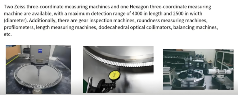
Ensuring the dimensional accuracy and surface quality of turbine impellers is critical. Five-axis machining centers integrate advanced inspection technologies to verify machining results. Common methods include:
- On-Machine Probing: Touch or laser probes measure key features, achieving measurement accuracies of ±0.005 mm.
- Coordinate Measuring Machines (CMMs): Offline inspection verifies tolerances and surface roughness values.
- Laser Scanning: Non-contact scanning generates point clouds for comparing machined surfaces to freeform models.
ignite integration with:
For instance, a five-axis setup might involve in-process probing to measure blade thickness and adjust toolpaths, reducing scrap rates by up to 15%. Post-machining CMM inspection ensures compliance with aerospace standards like AS9100, which mandate tight tolerances and traceability.