Machining accuracy is the degree of conformity between the actual size, shape, and positional geometric parameters of the machined part surface and the ideal geometric parameters required by the drawing.
The ideal geometric parameters are: for size, the nominal size; for surface geometric shape, absolute circle, cylinder, plane, cone and straight line, etc.;
for the mutual position between surfaces, absolute parallelism, perpendicularity, coaxiality, and symmetry, etc.
The deviation value between the actual geometric parameters and the ideal geometric parameters is called machining error.
What is machining accuracy
Machining accuracy is mainly used for evaluating the production level of products. Both machining accuracy and machining error are terms used to evaluate the geometric parameters of the machined surface. Machining accuracy is measured by tolerance grades; the smaller the grade value, the higher the accuracy. Machining error is expressed in numerical values; the larger the value, the greater the error. High machining accuracy means small machining error, and vice versa.
There are 20 tolerance grades from IT01, IT0, IT1, IT2, IT3 to IT18. IT01 indicates that the part has the highest machining accuracy, IT18 indicates the lowest machining accuracy, generally IT7 and IT8 are medium-grade machining accuracy.
Any machining method cannot obtain absolutely accurate actual parameters. From the perspective of part function, as long as the machining error is within the tolerance range required by the part drawing, the machining accuracy is considered guaranteed.
The quality of the machine depends on the machining quality of the parts and the assembly quality of the machine. The machining quality of parts includes two parts: machining accuracy and surface quality.
Machining accuracy refers to the degree of conformity between the actual geometric parameters (size, shape, and position) of the machined part and the ideal geometric parameters. The difference between them is called machining error. The size of the error reflects the level of machining accuracy. The greater the error, the lower the machining accuracy; the smaller the error, the higher the machining accuracy.
Related Content
Dimensional Accuracy
Refers to the degree of conformity between the actual size of the machined part and the center of the tolerance zone of the part size.
Shape Accuracy
Refers to the degree of conformity between the actual geometric shape of the machined surface and the ideal geometric shape.
Position Accuracy
Refers to the actual positional accuracy difference between related surfaces of the machined part.
Mutual Relationship
Generally, when designing machine parts and specifying part machining accuracy, attention should be paid to controlling the shape error within the position tolerance, and the position error should be less than the dimensional tolerance.
That is, for precision parts or important surfaces of parts, the shape accuracy requirements should be higher than the position accuracy requirements, and the position accuracy requirements should be higher than the dimensional accuracy requirements.
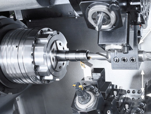
Adjustment Methods
1. Adjustment of the Process System
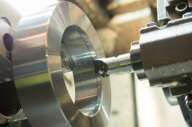
Trial Cutting Method Adjustment
Through trial cutting—measuring size—adjusting tool feed—cutting again—then trial cutting, repeating until the required size is achieved.
This method has low production efficiency and is mainly used for single-piece or small-batch production.
Adjustment Method
The required size is obtained by pre-adjusting the relative positions of the machine tool, fixture, workpiece, and tool.
This method has high productivity and is mainly used for mass production.
2. Reduce Machine Tool Errors
- Improve the manufacturing accuracy of spindle components:
- Select high-precision rolling bearings;
- Use high-precision multi-oil wedge hydrodynamic bearings;
- Use high-precision hydrostatic bearings.
- Improve the accuracy of parts matching with bearings:
- Improve the machining accuracy of the box support hole and spindle journal;
- Improve the machining accuracy of the surface matching the bearing;
- Measure and adjust the radial runout range of the corresponding parts to compensate or offset errors.
- Properly preload rolling bearings:
- Eliminate clearance;
- Increase bearing rigidity;
- Average rolling element errors.
- Make spindle rotation errors not reflect on the workpiece.
3. Reduce Transmission Chain Errors
- Fewer transmission elements, shorter chain, higher transmission accuracy;
- Use speed reduction transmission (i < 1), which is an important principle to ensure transmission accuracy; the closer to the end transmission pair, the smaller the transmission ratio should be;
- The accuracy of the end components should be higher than other transmission components.
4. Reduce Tool Wear
The tool must be reground before the tool size wear reaches the rapid wear stage.
5. Reduce Process System Deformation Under Load
- Improve system rigidity, especially weak links in the process system;
- Reduce load and its variation.
Improve System Rigidity
- Reasonable structural design:
- Minimize the number of connection surfaces;
- Prevent local low rigidity links;
- Reasonably select the structure and cross-sectional shape of the base and support parts.
- Improve the contact stiffness of the connection surface:
- Improve the quality of the joint surfaces between parts in machine tool components;
- Apply preload to machine tool components;
- Improve the accuracy of the positioning reference surface of the workpiece and reduce its surface roughness value.
- Adopt reasonable clamping and positioning methods.
Reduce Load and Its Variation
- Reasonably select tool geometry parameters and cutting parameters to reduce cutting force;
- Group blanks to make the machining allowance uniform during adjustment.
6. Reduce Process System Thermal Deformation
- Reduce heat sources and isolate them:
- Use smaller cutting parameters;
- Separate rough and finish machining when high part accuracy is required;
- Separate heat sources from the machine tool as much as possible to reduce machine thermal deformation;
- For unavoidable heat sources such as spindle bearings, screw-nut pairs, and high-speed moving guideway pairs, improve their friction characteristics in terms of structure and lubrication to reduce heating or use insulation materials;
- Use forced air or water cooling for heat dissipation.
- Balance the temperature field;
- Use reasonable machine component structure and assembly reference:
- Adopt thermally symmetrical structure—e.g., in the gearbox, symmetrically arrange shafts, bearings, and gears to make box wall temperature rise uniform and reduce deformation;
- Reasonably select the assembly reference of machine tool components.
- Accelerate thermal equilibrium;
- Control environmental temperature.
7. Reduce Residual Stress
- Add stress-relief heat treatment operations;
- Reasonably arrange the process flow.
Causes of Errors
- Machining Principle Error: Refers to the error caused by using an approximate cutting edge profile or an approximate transmission relationship. This error often occurs in thread, gear, and complex surface machining. For example, when machining involute gears with gear hobs, an Archimedean basic worm or a normal straight profile worm is used instead of an involute basic worm for convenience, causing errors in the involute tooth profile. Another example: when turning a module worm, since the worm lead equals the worm gear circumference (mπ), where m is the module and π is an irrational number, but the gear number of the lathe change gears is limited, π is approximated as a fractional value (π=3.1415) for calculation. This causes an inaccuracy in the forming motion (helical motion) between the tool and the workpiece, causing lead error. In machining, approximate machining is generally adopted to improve productivity and economy, as long as the theoretical error can meet machining accuracy requirements (≤10%~15% of dimensional tolerance).
- Adjustment Error: Refers to errors caused by inaccurate machine adjustments.
- Machine Tool Error: Refers to manufacturing, installation errors, and wear of the machine tool, mainly including guideway errors, spindle rotation errors, and transmission chain errors.
- Machine Tool Guideway Error:
- Guideway guiding accuracy—degree to which the actual motion direction of the moving part matches the ideal motion direction, mainly includes:
- Straightness Δy in the horizontal plane and Δz in the vertical plane (bending);
- Parallelism of the two guideways (twisting);
- Parallelism or perpendicularity errors of the guideway to the spindle rotation axis in the horizontal and vertical planes.
- The effect of guideway guiding accuracy on cutting mainly considers the relative displacement between the tool and workpiece caused by guideway errors in the sensitive direction.
In turning, the error sensitive direction is horizontal; in boring, it varies with tool rotation; in planing, the sensitive direction is vertical.
- Guideway guiding accuracy—degree to which the actual motion direction of the moving part matches the ideal motion direction, mainly includes:
- Machine Tool Spindle Rotation Error: Refers to the deviation of the actual rotation axis from the ideal rotation axis, including spindle end face runout, radial runout, and angular wobble.
- Spindle end face runout: no effect on turning cylindrical surfaces; in facing and boring end faces, causes perpendicularity or flatness error; in threading, causes pitch periodic errors.
- Radial runout: If radial rotation error shows harmonic linear motion along Y-axis, bored hole becomes elliptical with roundness error equal to radial runout amplitude; turning hole has no effect; eccentric motion causes a circle with radius equal to tool tip to average axis.
- Angular wobble: spindle geometric axis forms a conical trajectory relative to average axis, equivalent to eccentric motion with varying amplitude along the axis; actual spindle wobble is a superposition of these two types.
- Machine Tool Transmission Chain Error: Refers to the relative motion error between the first and last transmission elements in the chain.
- Fixture Manufacturing Error and Wear: Fixture errors mainly refer to: 1) manufacturing errors of locating elements, tool guiding elements, indexing mechanisms, fixture body; 2) relative dimensional errors of working surfaces of these elements after fixture assembly;3) wear of working surfaces during use.
- Tool Manufacturing Error and Wear: Tool errors affect machining accuracy differently depending on tool type: For fixed-size tools (drills, reamers, keyway milling cutters, broaches), size accuracy directly affects workpiece size accuracy. For forming tools (forming turning tools, milling cutters, grinding wheels), shape accuracy directly affects workpiece shape accuracy. For generating tools (gear hobs, spline hobs, gear shapers), cutting edge shape error affects workpiece shape accuracy. For general tools (turning, boring, milling tools), manufacturing accuracy has no direct effect, but tools wear easily.
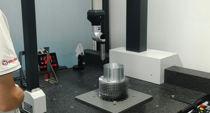
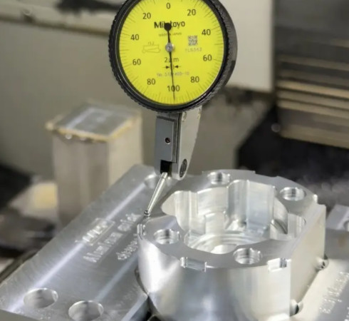
Measurement Methods
According to different machining accuracy contents and requirements, different measurement methods are used. Generally, there are the following types:
- By whether the measured parameter is directly measured: direct measurement and indirect measurement.
- Direct measurement: directly measure the parameter, e.g., caliper, comparator.Indirect measurement: measure related geometric parameters and calculate the measured size. Direct measurement is intuitive; indirect measurement is complicated and used when direct measurement cannot meet accuracy requirements.
- By whether the reading directly shows measured value: absolute measurement and relative measurement.
- Absolute: reading shows actual size directly (e.g., vernier caliper).Relative: reading shows deviation relative to standard size (e.g., comparator with gauge block reference). Relative measurement generally has higher accuracy but is more cumbersome.
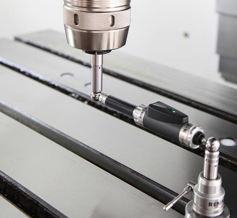
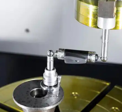
- By contact with measured surface: contact measurement and non-contact measurement.
- Contact: measuring head contacts surface with mechanical force (e.g., micrometer).
- Non-contact: measuring head does not contact surface (e.g., projection method, optical interference).
- By number of parameters per measurement: single and comprehensive measurement.
- Single: measure each parameter separately.Comprehensive: measure comprehensive indicators of related parameters (e.g., tool microscope measuring thread pitch error, flank angle error, etc.). Comprehensive measurement is efficient and reliable for interchangeability; single is used for process analysis, inspection, or specific parameters.
- By role during machining: active and passive measurement.
- Active: measure during machining; results used to control machining and prevent waste.
- Passive: measure after machining; only checks if part is qualified.
- By state of measured part: static and dynamic measurement.
- Static: measure at rest (e.g., micrometer diameter measurement).
- Dynamic: measure during relative motion simulating working condition; reflects actual usage, an advanced measurement technology trend.