The machining of intersecting lock pin holes in automotive front axles is a critical process in the manufacturing of high-performance vehicle components. Known as "broken hole drilling," this technique addresses the challenges of drilling intersecting holes in 50# steel with a hardness of 28–32 HRC. This article outlines a proven method, developed through extensive process trials, that ensures stable machining, minimizes tool wear, and achieves consistent hole quality. By optimizing tool selection, cutting edge preparation, and cutting parameters, this method overcomes issues such as uneven tool stress, chipping, and dimensional inaccuracies.
Component Overview and Machining Conditions
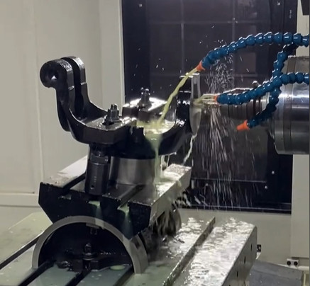
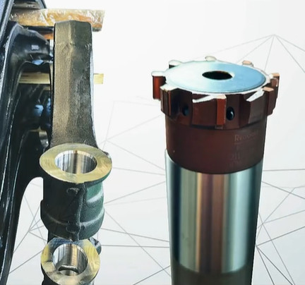
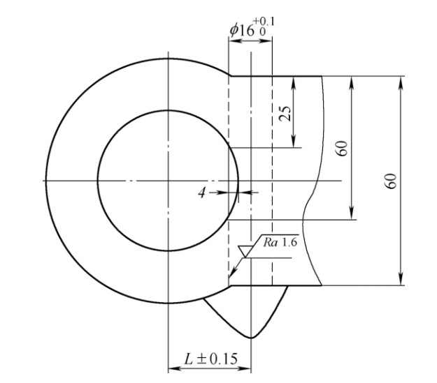
Automotive front axles commonly incorporate a lock pin structure, where the lock pin hole intersects with the kingpin hole. This design simplifies assembly and facilitates component replacement. The lock pin hole, with a diameter of φ16+0.1 mm and a surface roughness requirement of Ra=1.6 μm, must maintain a center distance tolerance of ±0.15 mm relative to the kingpin hole. The machining is performed on a dedicated machine equipped with internal cooling, hydraulic fixtures, and a hydraulic tool holder. The material is 50# steel, and drilling occurs on the blank surface, with each part requiring two lock pin holes.
Using standard drills for intersecting holes presents several issues:
- Hole Deviation and Dimensional Errors: Drilling at the intersection causes the drill to deviate, leading to oversized holes or positional inaccuracies.
- Surface Roughness Issues: The interrupted cut at the intersection results in poor surface finish, exceeding the Ra=1.6 μm requirement.
- Tool Chipping and Breakage: The impact at the intersection causes uneven forces, leading to drill chipping or breakage.
- Axial Force Fluctuation: At the intersection, the axial force decreases abruptly, causing the spindle and drill to surge forward, resulting in a "plunge" effect that affects hole quality.
To address these challenges, a series of process trials were conducted using solid carbide internal cooling drills, leading to the development of an optimized machining method.
Common Issues and Initial Tooling Trials
Initial trials with various tooling solutions revealed consistent limitations. The following approaches were tested, each highlighting specific shortcomings:
- Replaceable Head Drills or U-Drills: These drills experienced head detachment at the intersection due to the impact of broken hole drilling. The instability of the replaceable head made this approach unreliable for consistent production.
- Standard Carbide Internal Cooling Drills: Completing the drilling in a single pass was unstable, with frequent tool breakage and low tool life. The straightness and surface roughness of the holes were difficult to maintain within specifications.
- Carbide Internal Cooling Flat-Bottom Drills: These drills exhibited low machining efficiency and rapid tool wear, requiring frequent replacements. Worn drills caused vibrations, leading to deformed hole profiles and elliptical holes.
- Three-Flute Carbide Internal Cooling Drills: These provided better guidance and improved hole diameter stability. However, high cutting resistance and the impact of tool regrinding (resulting in a tapered drill profile) caused dimensional inconsistencies. Tools often failed to meet full inspection standards before reaching their expected lifespan, increasing costs.
These trials demonstrated that standard tooling solutions were inadequate for stable, high-quality machining of intersecting lock pin holes. A more refined approach was needed, focusing on tool design, cutting edge preparation, and process parameters.
Optimized Machining Methods
Through iterative testing and analysis, a comprehensive machining strategy was developed, combining multiple improvements to achieve stable, high-quality results. The following methods were implemented:
Method 1: Pilot Drilling for Enhanced Stability
A pilot drilling step was introduced using a specialized pilot drill (Drill ①), followed by the main drilling with a solid carbide internal cooling drill (Drill ②). The pilot drill ensures accurate centering, reducing the risk of deviation when the main drill reaches the intersection. This two-step process enhances tool durability and maintains hole diameter stability. The pilot drill is designed to create a stable entry point, guiding the subsequent carbide drill through the complex geometry of the intersecting hole.
Method 2: Cutting Edge Optimization
The cutting edge of the carbide drill was refined to improve wear resistance and machining stability. The following modifications were made:
- Transverse Edge Design: A horizontal cutting edge was adopted to distribute cutting forces more evenly, reducing stress concentration at the intersection.
- Chamfered Tip: A chamfered tip was introduced to minimize chipping during the initial contact with the material.
- Edge Blunting: Controlled blunting of the cutting edge was applied to enhance durability, preventing premature wear or chipping at the intersection.
These modifications significantly improved the drill’s ability to withstand the impact of broken hole drilling, ensuring consistent performance throughout its lifespan.
Method 3: Segmented Feed Rate Strategy
Optimized cutting parameters were critical to achieving stable machining. A five-stage segmented feed rate strategy was implemented to adapt to the varying conditions encountered during drilling, particularly at the intersection. The parameters for a φ16 mm carbide drill are as follows:
| Depth (mm) | Feed Rate (mm/r) | Cutting Speed (m/min) | Description |
|---|---|---|---|
| 0–25 | 0.15 | 60 | Initial drilling phase, stable material removal |
| 25–60 | 0.10 | 60 | Intersection phase, reduced feed to protect tool |
| 60–End | 0.15 | 60 | Post-intersection, restored feed for efficiency |
This segmented approach reduces the feed rate at the intersection (25–60 mm depth), minimizing tool stress and preventing the "plunge" effect. After passing the intersection, the feed rate is restored to maintain efficiency. This strategy enhances tool life and ensures dimensional accuracy and surface quality.
Method 4: Adjusted Drill Diameter
To address the issue of drill taper after regrinding, the drill diameter was increased from φ16.04 mm to φ16.07 mm. This adjustment compensates for the dimensional changes caused by regrinding, ensuring that the hole diameter remains within the φ16+0.1 mm tolerance throughout the tool’s lifespan. This modification extended the average tool life and improved dimensional consistency.
Results and Performance Improvements
The optimized machining methods were rigorously tested and implemented in production, yielding significant improvements:
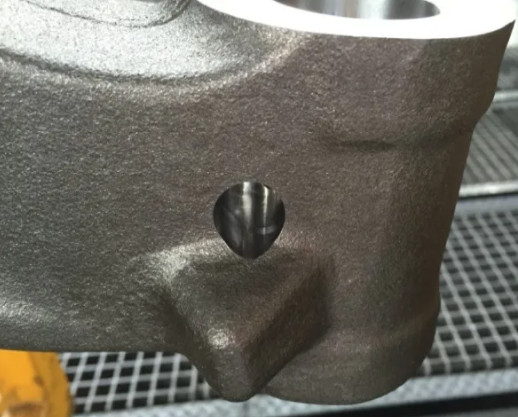
- 100% Hole Diameter Compliance: All machined holes met the φ16+0.1 mm specification, with no instances of oversizing or positional errors.
- Stable Intersection Distance: The center distance between the kingpin and lock pin holes consistently met the ±0.15 mm tolerance.
- Improved Tool Life: The average tool life increased to 50–60 parts per drill, with the ability to regrind the drill 5–6 times, significantly reducing tooling costs.
- Enhanced Efficiency: The optimized process improved machining efficiency by 33%, reducing cycle times while maintaining quality.
- Consistent Surface Quality: The surface roughness achieved the required Ra=1.6 μm, with no deviations observed during production.
The combination of pilot drilling, cutting edge optimization, segmented feed rates, and adjusted drill diameters ensured stable machining conditions, eliminating issues such as tool chipping, breakage, and dimensional inaccuracies.
Implementation in Production
The optimized machining process was seamlessly integrated into production, with the following outcomes:
| Metric | Before Optimization | After Optimization |
|---|---|---|
| Hole Diameter Compliance | Inconsistent | 100% |
| Tool Life (Parts per Drill) | 20–30 | 50–60 |
| Regrinding Cycles | 2–3 | 5–6 |
| Machining Efficiency | Baseline | +33% |
| Surface Roughness (Ra) | Occasionally >1.6 μm | Consistently 1.6 μm |
The process demonstrated robustness across multiple production batches, with no significant variations in performance. The use of hydraulic fixtures and internal cooling further enhanced stability, ensuring repeatable results under high-volume manufacturing conditions.
Conclusion
The machining of intersecting lock pin holes in automotive front axles requires a systematic approach to overcome the challenges of uneven tool stress, chipping, and dimensional inaccuracies. Through extensive process trials, a combination of pilot drilling, optimized cutting edge preparation, segmented feed rates, and adjusted drill diameters was developed. This method achieves 100% dimensional compliance, extends tool life by up to 200%, and improves machining efficiency by 33%. The process is now a reliable standard for high-quality production, demonstrating the value of iterative testing and precise parameter control in complex machining applications.