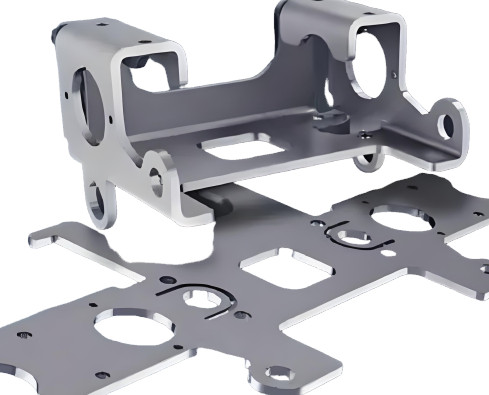
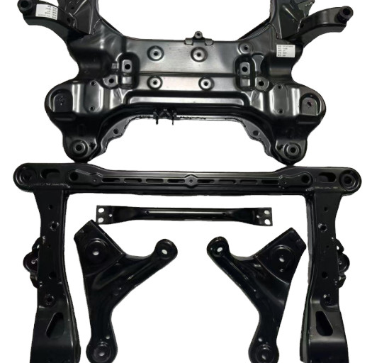
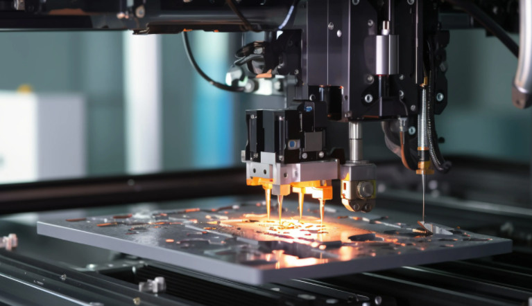
Sheet metal machining is a critical manufacturing process used to create precise components from thin metal sheets. It involves various techniques such as cutting, bending, forming, and assembling to produce parts for industries like automotive, aerospace, electronics, and construction. This comprehensive guide covers the essential methods, tools, parameters, and considerations for effective sheet metal machining, providing technical insights for professionals and manufacturers.
Understanding Sheet Metal Machining
Sheet metal machining transforms flat metal sheets, typically ranging from 0.5 mm to 6 mm in thickness, into desired shapes and sizes. The process requires precision to meet tight tolerances, often within ±0.1 mm, depending on the application. Common materials include steel, aluminum, stainless steel, copper, and brass, each chosen for specific properties like strength, corrosion resistance, or conductivity.
The process involves multiple stages, from design and material selection to cutting, forming, and finishing. Each stage demands specialized tools and techniques to ensure quality and efficiency. Below, we explore the primary methods and their applications in detail.

Key Techniques in Sheet Metal Machining
Sheet metal machining encompasses several techniques, each suited to specific tasks. The choice of method depends on factors like material type, thickness, part complexity, and production volume.
Cutting Techniques
Cutting is the initial step in shaping sheet metal. It involves removing material to create contours, holes, or slots. Common cutting methods include:
- Shearing: A mechanical process using a straight blade to cut sheet metal along a linear path. Suitable for simple shapes, shearing is cost-effective for low-volume production. Typical shear force ranges from 10 to 50 tons, depending on material thickness and type.
- Laser Cutting: Utilizes a high-powered laser (e.g., CO2 or fiber laser) to melt or vaporize metal. Fiber lasers, with power outputs of 2–6 kW, achieve cutting speeds up to 20 m/min for 1 mm steel. Laser cutting offers precision within ±0.05 mm, ideal for intricate designs.
- Plasma Cutting: Employs ionized gas to cut conductive metals. Effective for thicker sheets (up to 50 mm), plasma cutting achieves speeds of 0.5–2 m/min with tolerances of ±0.5 mm.
- Waterjet Cutting: Uses a high-pressure water stream mixed with abrasives to cut metal. It is versatile for materials like aluminum and stainless steel, with tolerances of ±0.1 mm. Waterjet cutting is slower (0.1–1 m/min) but produces no heat-affected zones.
Forming Techniques
Forming reshapes sheet metal without removing material. Key forming methods include:
- Bending: Performed using press brakes, bending applies force to create angles or curves. Press brakes with capacities of 50–300 tons handle sheets up to 6 mm thick. Bend radii typically range from 1 to 5 times the material thickness to avoid cracking.
- Roll Forming: Continuously bends metal through a series of rollers to create profiles like channels or tubes. Roll forming is efficient for long, uniform parts, with speeds up to 30 m/min.
- Stamping: Uses dies and presses to form shapes, emboss, or punch features. Stamping presses (50–1000 tons) are ideal for high-volume production, achieving cycle times as low as 0.5 seconds per part.
- Deep Drawing: Stretches sheet metal into deep, hollow shapes like cans or enclosures. The process requires a draw ratio (blank diameter to part depth) of 1.5–2.5 to prevent tearing.
Assembly and Joining Techniques
Joining combines sheet metal parts into final assemblies. Common methods include:
- Welding: Techniques like MIG, TIG, and spot welding fuse metal parts. TIG welding, using currents of 50–200 A, ensures high-quality joints for stainless steel and aluminum.
- Riveting: Uses metal fasteners to join sheets. Rivet diameters range from 3 to 10 mm, suitable for structural applications.
- Adhesive Bonding: Employs structural adhesives for lightweight assemblies, offering bond strengths up to 20 MPa.
- Clinching: Mechanically interlocks sheets without fasteners, ideal for thin sheets (0.5–2 mm).
Tools and Equipment for Sheet Metal Machining
Effective sheet metal machining relies on specialized tools and equipment designed for precision and efficiency. Below is a table summarizing key tools and their specifications:
| Tool/Equipment | Purpose | Key Specifications |
|---|---|---|
| CNC Press Brake | Bending and forming | 50–300 tons, 2–4 m bed length, ±0.1 mm accuracy |
| Fiber Laser Cutter | Precision cutting | 2–6 kW, 0.05 mm tolerance, 20 m/min speed |
| Turret Punch Press | Punching and forming | 20–50 tons, 30–60 punches/min, ±0.1 mm accuracy |
| Roll Forming Machine | Continuous forming | 10–30 m/min, handles 0.5–3 mm thickness |
| TIG Welder | Joining | 50–200 A, suitable for 0.5–6 mm sheets |
Material Selection and Properties
Choosing the right material is crucial for sheet metal machining. The table below outlines common materials and their properties:
| Material | Thickness Range (mm) | Key Properties | Applications |
|---|---|---|---|
| Steel (Mild) | 0.5–6 | High strength, cost-effective | Automotive panels, enclosures |
| Stainless Steel | 0.5–4 | Corrosion-resistant, durable | Medical equipment, kitchenware |
| Aluminum | 0.5–5 | Lightweight, conductive | Aerospace components, electronics |
| Copper | 0.5–3 | High conductivity | Electrical components |
| Brass | 0.5–3 | Corrosion-resistant, aesthetic | Decorative parts, fittings |
Process Parameters and Optimization
Optimizing machining parameters ensures quality and efficiency. Key parameters include:
- Cutting Speed: For laser cutting, speeds range from 0.5–20 m/min, depending on material and thickness. Higher speeds reduce heat input but may compromise edge quality.
- Tooling Clearance: In punching, clearance between punch and die (typically 5–10% of material thickness) affects edge quality and tool life.
- Bending Force: Calculated as F = (k × L × T² × S) / W, where k is a constant (1.2–1.5), L is bend length (mm), T is thickness (mm), S is tensile strength (MPa), and W is die opening (mm).
- Welding Current: For TIG welding, currents of 50–150 A are used for 1–3 mm sheets to balance penetration and heat input.
Quality Control and Inspection
Quality control ensures parts meet specifications. Common inspection methods include:
- Coordinate Measuring Machines (CMM): Measure dimensions with ±0.01 mm accuracy.
- Surface Roughness Testing: Ensures surface finish meets standards (e.g., Ra 0.8–3.2 µm for polished surfaces).
- Non-Destructive Testing (NDT): Techniques like ultrasonic testing detect internal defects in welds.

FAQ
What is the best cutting method for sheet metal?
Laser cutting is often preferred for its precision (±0.05 mm) and versatility, but plasma or waterjet cutting may be better for thicker materials or specific applications.
How do I choose the right sheet metal material?
Consider factors like strength, corrosion resistance, weight, and conductivity. For example, aluminum is ideal for lightweight applications, while stainless steel suits corrosive environments.
What tolerances can sheet metal machining achieve?
Tolerances vary by process: laser cutting achieves ±0.05 mm, bending ±0.1 mm, and punching ±0.1–0.2 mm, depending on equipment and material.
