
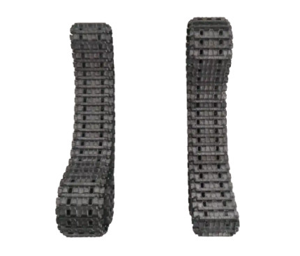
Track shoes are critical components in the mobility systems of armored vehicles, serving as the primary load-bearing and traction elements. The machining of track shoe components, particularly those with an integrated structure, presents significant technical difficulties due to their complex geometry, material properties, and stringent precision requirements. This article provides a comprehensive analysis of the machining challenges associated with track shoe components and outlines a cost-effective, efficient processing scheme developed through practical trials. The focus is on addressing the difficulties in drilling, boring, and chamfering processes, with detailed insights into tool selection, fixture design, and cutting parameters.
Technical Requirements of Track Shoe Components
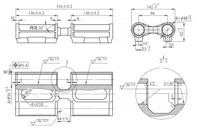
The track shoe under discussion is made from 42CrMo steel, starting as a forged blank with a hardness of 200–240 HBW. After heat treatment, the hardness increases to 401–461 HBW to meet final machining requirements. The component has outer dimensions of (316 ± 0.3) mm and (142 ± 1.5) mm. Key machining features include four φ34 mm pin holes with chamfers at both ends, requiring a coaxiality of ≤0.2 mm and positional accuracy of ≤0.4 mm to ensure a minimum end wall thickness of >6.7 mm. Additionally, 100% non-destructive testing is mandatory to verify structural integrity.
These specifications demand high precision and robust process control to achieve dimensional accuracy, surface quality, and structural reliability. The combination of material hardness, tight tolerances, and complex geometry necessitates a systematic approach to machining.
Process Design for Track Shoe Machining
The machining process is divided into two main stages: rough machining before heat treatment and finish machining after heat treatment. Each stage addresses specific requirements to ensure efficiency, quality, and cost-effectiveness.
Rough Machining Stage
Rough machining focuses on establishing datum surfaces and preparing the workpiece for heat treatment. The process includes machining the bottom and side surfaces to serve as reference datums, ensuring dimensional tolerances for the 316 mm end faces and the central recess. The side surfaces, which are not machined after quenching, must meet final dimensional tolerances during this stage. The four φ34 mm pin holes are rough-drilled to φ32 mm, maximizing material removal efficiency while maintaining positional accuracy relative to the datum surfaces. This stage also involves inspecting the forged blank for defects to minimize material waste.
Finish Machining Stage
After heat treatment, the finish machining stage restores the datum references and achieves the final precision requirements. The process prioritizes the accuracy of the four pin holes, including their coaxiality (≤0.2 mm) and positional tolerance (≤0.4 mm). To enhance efficiency, boring and chamfering are ideally completed in a single setup to reduce workpiece handling and setup changes. The finish machining process leverages advanced tooling and fixturing to meet surface roughness requirements (Ra = 1.6 µm) and ensure defect-free results.
Machining Difficulties and Solutions
The machining of track shoe components presents several technical challenges, particularly in drilling, boring, and chamfering. The following sections detail these difficulties and the solutions implemented to address them.
Drilling of Four φ34 mm Pin Holes
Rough drilling the four φ34 mm pin holes to φ32 mm before heat treatment is a critical step. The challenge lies in balancing processing efficiency, tool durability, and cost. Three drilling methods were evaluated:
- Radial Drilling with Jig: Using a radial drill with a standard high-speed steel (HSS) extended drill bit. This method is cost-effective but labor-intensive, requiring skilled operators for tool sharpening, and offers low efficiency.
- Deep Hole Drilling: This method provides high efficiency but requires specialized equipment or outsourcing, increasing costs and complexity.
- CNC Vertical Machining Center with U-Drill: Utilizing a U-drill on a vertical machining center offers versatility, high efficiency, and compatibility with existing equipment.
After evaluation, the third method was selected. The company’s Youjia NBP-1100A vertical machining center, equipped with an 8 MPa center coolant system, was chosen for its suitability for internal hole machining. A φ32 mm ZTD05 series U-drill from Zhuzhou Diamond was selected, featuring a spiral internal cooling structure and large chip evacuation space, enabling high-feed cutting. The U-drill uses YBG212 inserts for the inner cutting edge, offering high toughness for low-speed conditions, and YBG205 inserts for the outer edge, providing excellent wear resistance. This combination ensures tool life and stability when machining 42CrMo steel.
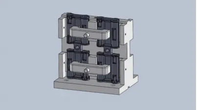
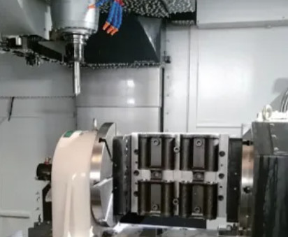
To ensure process stability, a dedicated drilling fixture was designed (see Figure 5 in the original reference). The fixture provides consistent workpiece clamping and enhances the rigidity of the machining system, accommodating the production cycle and part geometry.
Boring of Four φ34 mm Pin Holes
Finish machining the φ34 mm pin holes requires achieving a coaxiality of ≤0.2 mm, positional accuracy of ≤0.4 mm, and a surface roughness of Ra = 1.6 µm. Given the component’s 316 mm length, single-direction machining is impractical, necessitating a flip-over approach. A four-axis rotary table was employed, allowing workpiece flipping within a single setup. A custom fixture with side and bottom datum positioning was designed to machine two workpieces simultaneously, processing both front and back faces.
Two boring methods were considered: rough boring followed by reaming, or rough boring followed by finish boring. Due to the long lead time for custom alloy reamers, the rough and finish boring approach was selected. High-rigidity solid carbide toolholders and durable cutting inserts were used to ensure precision and efficiency.
Chamfering of Pin Hole Recess Surfaces
Chamfering the pin holes, particularly at the central recess with 5×30° and 2×45° chamfers, poses a significant challenge. Separate chamfering operations would increase labor and equipment demands, reducing efficiency. Additionally, chamfering after boring can introduce burrs inside the hole, which are difficult to remove and may damage rubber components during assembly. To address this, a custom tool was designed to perform chamfering simultaneously with finish boring. Three chamfering methods were evaluated:
- Detachable Composite Chamfering Tool: This tool is cost-effective and simple but requires manual tool changes, reducing efficiency.
- Eccentric Back-Boring Chamfering Tool: This tool uses the machining center’s orientation function to rotate the tool tip to a set angle, allowing eccentric entry into the hole. After reaching the hole bottom, the tool aligns with the hole center, enabling back-boring of the chamfer.
- Imported Automatic Back-Scraping Tool: This tool uses a clutch mechanism to deploy and retract the cutting blade. While efficient, it requires two custom tools for 30° and 45° chamfers, with high costs and long procurement lead times.
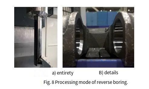
The eccentric back-boring chamfering tool was selected for its balance of efficiency and cost. The tool is designed with a φ33 mm bottom diameter to pass through the φ34 mm hole, with a 0.5 mm single-side clearance. For the 5×30° chamfer (maximum diameter ≈ φ40 mm), the tool’s rotational radius is 20.5 mm, with a 4 mm cutting edge width and 4 mm eccentricity. The maximum toolholder diameter is calculated as 33 – 20.5 + (20.5 – 4) = 29 mm. The chamfering process uses back-boring, as shown in Figure 8 of the original reference, ensuring precise and burr-free results.
Process Parameters for Finish Machining
The finish machining parameters for boring and chamfering are critical to achieving the required precision and surface quality. The following table summarizes the key parameters:
| Operation | Tool Type | Spindle Speed (RPM) | Feed Rate (mm/min) | Depth of Cut (mm) |
|---|---|---|---|---|
| Rough Boring | Solid Carbide Toolholder | 800 | 100 | 0.5 |
| Finish Boring | Solid Carbide Toolholder | 1000 | 80 | 0.2 |
| Chamfering (Back-Boring) | Eccentric Chamfering Tool | 500 | 30 | 0.5 |
The chamfering process uses a specific CNC program to ensure precise tool positioning and movement, as follows:
G290
T23 M6 (Tool Change)
G0 G90 A180 (A-axis positioning 180°)
SPOS=150 (Spindle orientation 150°)
G90 G54 X-130.7 Y-25.3 (Move to first hole eccentric position)
M8 (Coolant on)
Z100 (Safe height)
G01 Z-156 F3000 (Tool entry)
X-135.7 F500 (Move to hole center)
M3 S500 (Spindle forward rotation)
Z-148.5 G01 F30 (Back-boring chamfer)
Z-156 F3000 (Retract)
M05 (Stop spindle)
SPOS=150 (Spindle orientation 150°)
X-130.9 (Move to eccentric position)
Z100 F3000 (Return to safe height)
…
G291
Conclusion
The machining of track shoe components requires addressing complex challenges in drilling, boring, and chamfering while balancing quality, efficiency, and cost. Through systematic process design, tool selection, and fixture development, a practical solution was developed for medium-batch production. The use of a vertical machining center with U-drills, custom boring tools, and eccentric chamfering tools enabled efficient and precise machining. The process achieves a daily output of 60 components, meeting annual production demands. Additionally, the development of custom tools and fixtures provides flexibility for machining similar components by adjusting parameters, paving the way for potential automation in large-scale production.