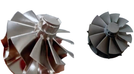
High-temperature alloy impellers, critical components in aerospace and industrial applications, require precise polishing to achieve optimal surface quality, aerodynamic performance, and fatigue resistance. This guide outlines a systematic approach to optimizing the polishing process for high-temperature alloy impellers, focusing on technical steps, detailed parameters, and practical considerations. The process is tailored to nickel-based alloys (e.g., Inconel 718) and titanium alloys (e.g., Ti-6Al-4V), which are commonly used due to their strength and heat resistance. The following steps ensure a reproducible, high-quality surface finish while maintaining dimensional accuracy and material integrity.
Step 1: Initial Surface Preparation
Before polishing, the impeller surface must be prepared to remove defects from prior manufacturing processes, such as casting, machining, or additive manufacturing. High-temperature alloys often exhibit surface irregularities, including burrs, oxide layers, and machining marks, which must be addressed to ensure uniform polishing.
Process Details:
- Grinding: Begin with mechanical grinding using silicon carbide (SiC) abrasive papers. Start with a coarse grit (e.g., 400 grit [P800]) for 60 seconds, followed by a finer grit (e.g., 600 grit [P1200]) for another 60 seconds. Use a grinding machine at 150 rpm with water-based lubrication to minimize heat generation.
- Cleaning: Perform ultrasonic cleaning to remove abrasive particles and debris. For alloys with pores or cracks, limit cleaning to 5–10 minutes at 40 kHz to avoid structural damage.
- Inspection: Use optical microscopy to assess surface uniformity. Measure surface roughness (Ra) with a profilometer, targeting an initial Ra of 1.5–2.0 μm before proceeding.
Parameters:
| Process | Abrasive | Grit Size | Time (s) | Speed (rpm) | Lubricant |
|---|---|---|---|---|---|
| Grinding | SiC Paper | 400, 600 | 60 per grit | 150 | Water |
| Ultrasonic Cleaning | N/A | N/A | 300–600 | 40 kHz | Neutral Solution |
Considerations: Excessive grinding can introduce subsurface damage, while insufficient cleaning may leave contaminants that affect subsequent polishing. For additive-manufactured impellers, address spheroidization (Ra > 8 μm) with extended grinding.
Step 2: Mechanical Polishing
Mechanical polishing reduces surface roughness and prepares the impeller for final finishing. This step uses fine abrasives and controlled conditions to minimize deformation and achieve a smooth surface. For high-temperature alloys, vibratory polishing is often preferred due to its gentle material removal.
Process Details:
- Abrasive Selection: Use diamond slurries (1 μm) or colloidal silica suspensions (0.05 μm) with a pH of ~10. Diamond is effective for initial polishing, while colloidal silica provides a chemo-mechanical action for softer alloys.
- Equipment: Employ a vibratory polisher with a medium-nap cloth (e.g., wool or flocked plastic). Set the frequency to 15–50 Hz, depending on impeller mass, and polish for 2–6 hours.
- Lubrication: Apply a water-based lubricant to keep the cloth moist, not wet, to prevent abrasive loss. Maintain a polishing pressure of 20–30 N for six 30 mm diameter samples.
- Monitoring: Measure Ra after each hour of polishing. Target Ra of 0.5–0.8 μm before proceeding to the next step.
Parameters:
- Abrasive: 1 μm diamond slurry or 0.05 μm colloidal silica
- Cloth: Medium-nap wool or flocked plastic
- Frequency: 15–50 Hz
- Time: 2–6 hours
- Pressure: 20–30 N
- Lubricant: Water-based, pH ~10
Considerations: High-temperature alloys like Inconel 718 may have hard oxide layers that require extended polishing time. Avoid overheating (>60°C) to prevent surface tarnishing or warping of thin-walled sections.
Step 3: Chemical or Electrochemical Polishing
Chemical or electrochemical polishing removes microscopic surface irregularities and enhances surface smoothness. Electropolishing is particularly effective for high-temperature alloys, as it provides a deformation-free finish suitable for crystallographic analyses.
Process Details:
- Electropolishing Setup: Use an electropolishing system (e.g., ElectroMet 4) with a stainless steel cathode. Set the voltage to 30 Vdc and polish for 60 seconds in an electrolyte containing 10% perchloric acid and 90% methanol at <38°C.
- Chemical Polishing Alternative: For non-conductive areas, use a solution of phosphoric acid (H3PO4), hydrogen peroxide (H2O2), and nicotinic acid. Immerse the impeller for 1.5 hours at 140 rpm with 1.2 mm SiC abrasives (600 mL/L).
- Safety: Handle perchloric acid with care, avoiding contact with organic materials to prevent unstable perchlorate formation. Use fume hoods and temperature-controlled systems.
- Inspection: Achieve Ra of 0.1–0.4 μm. Use scanning electron microscopy (SEM) to verify the absence of wavy surfaces or rounded edges.
Parameters:
| Process | Electrolyte | Voltage (Vdc) | Time (s) | Temperature (°C) | Abrasive |
|---|---|---|---|---|---|
| Electropolishing | 10% Perchloric Acid, 90% Methanol | 30 | 60 | <38 | N/A |
| Chemical Polishing | H3PO4, H2O2, Nicotinic Acid | N/A | 5400 | Ambient | 1.2 mm SiC |
Considerations: Electropolishing may preferentially attack multi-phase alloys, requiring precise voltage control. Chemical polishing is slower but suitable for complex geometries.
Step 4: Abrasive Flow Machining (AFM) for Internal Channels
Impellers with internal channels or vanes require specialized finishing to reduce surface roughness and improve hydraulic efficiency. Abrasive flow machining (AFM) is ideal for polishing intricate, out-of-sight surfaces.
Process Details:
- Media: Use a viscous elastic media loaded with 80 mesh SiC abrasives at 20% concentration. The media flows back and forth through the impeller channels under 8 MPa pressure for 15 minutes.
- Tooling: Design custom tooling to hold the impeller securely and direct media flow through all vanes in a single operation.
- Outcome: Reduce Ra from 8.186 μm to 0.422 μm, eliminating casting residuals and improving laminar flow.
- Verification: Use surface morphology analysis to confirm uniform material removal and absence of spheroidization.
Parameters:
- Abrasive: 80 mesh SiC
- Concentration: 20%
- Pressure: 8 MPa
- Time: 15 minutes
- Media: Viscous elastic
Considerations: AFM is effective for additive-manufactured impellers but requires precise tooling to avoid uneven polishing. Regular media replacement ensures consistent abrasive action.
Step 5: Final Inspection and Passivation
The final step involves rigorous inspection and surface treatment to ensure the impeller meets performance requirements and resists corrosion in high-temperature environments.
Process Details:
- Surface Roughness: Measure Ra using a white light profilometer, targeting <0.4 μm. Verify uniformity across blades and channels.
- Microstructure: Use electron backscatter diffraction (EBSD) to confirm a deformation-free surface, critical for fatigue resistance.
- Passivation: Treat with nitric acid (20–40%) for 30 minutes to form a dense oxide layer, enhancing corrosion resistance (e.g., 316L stainless steel pitting potential increases by >300 mV).
- Coating (Optional): Apply a diamond-like carbon (DLC) coating to reduce friction (coefficient of 0.05) for specific applications.
Parameters:
- Ra Target: <0.4 μm
- Passivation Solution: 20–40% Nitric Acid
- Passivation Time: 30 minutes
- Coating: DLC (optional)
Considerations: Passivation must be carefully controlled to avoid dimensional changes. Coating adhesion requires a mirror-like surface (Ra <0.05 μm).

Conclusion
Optimizing the polishing process for high-temperature alloy impellers involves a systematic sequence of initial preparation, mechanical polishing, chemical or electrochemical polishing, abrasive flow machining, and final inspection with passivation. Each step is supported by specific parameters and equipment to achieve a surface roughness of <0.4 μm, ensuring aerodynamic efficiency, fatigue durability, and corrosion resistance. By following this structured approach, manufacturers can produce impellers that meet stringent aerospace and industrial standards with consistent, high-quality results.