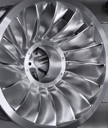
Precision machining of turbine blades is critical for the performance, efficiency, and reliability of turbine engines. This guide provides a detailed, systematic approach to achieving high machining accuracy through optimized methods, parameters, and techniques.
Importance of Machining Precision in Turbine Blades
Turbine blades operate under extreme conditions, including high temperatures (up to 2200 K), pressures, and rotational speeds (often exceeding 12,000 rpm). Precise machining ensures dimensional accuracy, surface integrity, and structural strength, directly impacting engine efficiency and longevity. For instance, a dimensional deviation as small as 0.01 mm can lead to increased vibration, reduced aerodynamic performance, or premature fatigue failure. Achieving tight tolerances, typically within ±0.005 mm for critical features, is essential to meet these demands.
Precision also affects cooling efficiency in blades with internal cooling channels. Inaccurate machining of these channels, which often have diameters as small as 0.5 mm, can disrupt airflow, leading to thermal imbalances. This section outlines the technical foundation for optimizing machining processes to meet these stringent requirements.

Key Machining Processes for Turbine Blades
Turbine blades are typically manufactured using advanced materials like nickel-based superalloys, titanium alloys, or ceramic matrix composites. These materials pose challenges due to their high hardness, low thermal conductivity, and tendency to work-harden. The primary machining processes include:
- Creep Feed Grinding: Used for shaping blade profiles, offering high material removal rates with surface roughness values as low as Ra 0.4 µm.
- Electro-Discharge Machining (EDM): Ideal for intricate cooling holes, achieving tolerances of ±0.003 mm.
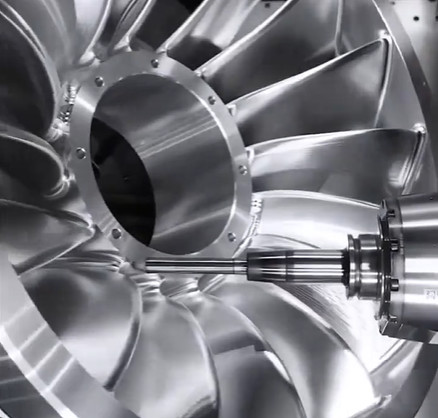
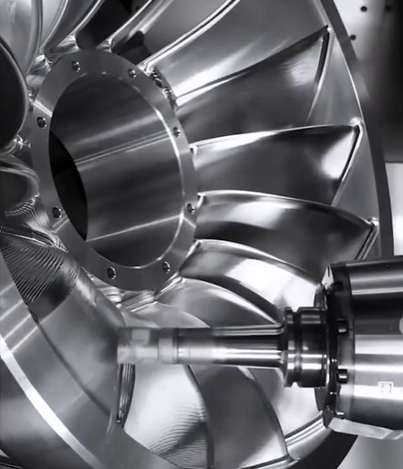
- Five-Axis CNC Milling: Employed for complex geometries, with positional accuracy up to ±0.002 mm.
- Laser Drilling: Used for micro-holes in cooling channels, with hole diameters ranging from 0.2 to 1.0 mm.
Each process requires specific parameter optimization to balance precision, efficiency, and tool life. For example, creep feed grinding uses wheel speeds of 20–30 m/s and feed rates of 0.5–2 mm/min to minimize thermal damage while maintaining dimensional accuracy.
Optimization Methods for Machining Precision
Optimizing machining precision involves a combination of process control, parameter adjustment, and advanced technologies. The following methods are critical for achieving high accuracy:
Process Parameter Optimization
Selecting optimal machining parameters is fundamental. For instance, in five-axis CNC milling, spindle speeds of 10,000–15,000 rpm, feed rates of 0.1–0.3 mm/rev, and depth of cut of 0.05–0.2 mm are typical for nickel-based alloys. These parameters reduce tool deflection and surface irregularities. In EDM, pulse duration (10–50 µs) and current (5–20 A) are adjusted to control material removal rates and minimize recast layers, which can affect fatigue life.
Table 1 below summarizes recommended parameters for key processes:
| Process | Parameter | Range | Purpose |
|---|---|---|---|
| Creep Feed Grinding | Wheel Speed | 20–30 m/s | Minimize thermal damage |
| Five-Axis CNC Milling | Spindle Speed | 10,000–15,000 rpm | Reduce tool deflection |
| EDM | Pulse Duration | 10–50 µs | Control recast layer thickness |
| Laser Drilling | Pulse Energy | 0.5–2 J | Achieve precise hole geometry |
Tool Selection and Maintenance
Tool material and geometry significantly influence precision. For grinding, cubic boron nitride (CBN) wheels with grain sizes of 80–120 mesh are preferred for their durability and ability to maintain sharpness. In milling, coated carbide tools with TiAlN coatings reduce wear at cutting temperatures up to 800°C. Regular tool inspection, using techniques like optical microscopy or laser scanning, ensures edge integrity and prevents dimensional errors.
Tool wear monitoring systems, integrated with CNC machines, can detect deviations in cutting forces (e.g., increases beyond 10% of baseline) to prompt timely tool replacement. This approach extends tool life by 20–30% while maintaining tolerances.

Advanced Metrology and Inspection
Post-machining inspection verifies dimensional accuracy and surface quality. Coordinate Measuring Machines (CMMs) with probing accuracy of ±0.001 mm are used to measure critical features like blade chord length and airfoil thickness. Non-contact methods, such as laser scanning, capture complex freeform surfaces with point cloud densities up to 100,000 points/cm², enabling comparison against CAD models.
Surface roughness is assessed using profilometers, targeting Ra values of 0.2–0.8 µm for aerodynamic surfaces. For cooling holes, X-ray computed tomography (CT) evaluates internal geometry, detecting deviations in hole diameter or alignment as small as 0.01 mm.
Simulation and Modeling
Finite Element Analysis (FEA) and Computational Fluid Dynamics (CFD) simulations predict machining outcomes. FEA models tool-workpiece interactions, optimizing parameters to minimize residual stresses (typically below 200 MPa). CFD analyzes coolant flow in grinding, ensuring effective heat dissipation at contact zones where temperatures can reach 1000°C. These simulations reduce trial-and-error, cutting development time by up to 25%.
Techniques for Enhancing Surface Integrity
Surface integrity, encompassing roughness, residual stresses, and microstructure, is critical for blade performance. Poor surface integrity can reduce fatigue life by 30–50%. The following techniques enhance surface quality:
Controlled Coolant Application
High-pressure coolant systems (50–100 bar) improve chip evacuation and reduce thermal distortion in grinding and milling. Minimum Quantity Lubrication (MQL) with vegetable-based oils minimizes environmental impact while maintaining surface roughness below Ra 0.6 µm. Coolant flow rates of 10–20 L/min are typical for creep feed grinding to prevent burn marks.
Post-Processing Treatments
Shot peening introduces compressive residual stresses (up to -600 MPa) to enhance fatigue resistance. Abrasive flow machining polishes internal cooling channels, reducing surface roughness from Ra 1.6 µm to Ra 0.4 µm. These treatments extend blade life by 15–20% under cyclic loading conditions.
Adaptive Machining
Adaptive machining uses real-time feedback from sensors to adjust parameters. For example, in-process monitoring of cutting forces (via dynamometers) allows dynamic adjustment of feed rates to maintain tolerances within ±0.003 mm. This technique is particularly effective for large blades with diameters exceeding 3 m, where thermal expansion can cause deviations.
Quality Control and Standardization
Robust quality control ensures consistency across production batches. Standards like ISO 1101 (for geometric dimensioning and tolerancing) and ASME Y14.5 guide tolerance specifications. For aerospace applications, compliance with International Civil Aviation Organization (ICAO) regulations mandates certified inspection processes.
Statistical Process Control (SPC) monitors machining variables, using control charts to detect trends (e.g., shifts exceeding 3σ). Capability indices like Cp and Cpk, targeting values ≥1.33, confirm process reliability. Regular calibration of equipment, performed every 6 months, maintains measurement accuracy.
Table 2 outlines key quality control metrics:
| Metric | Target Value | Purpose |
|---|---|---|
| Surface Roughness (Ra) | 0.2–0.8 µm | Ensure aerodynamic efficiency |
| Tolerance | ±0.005 mm | Maintain dimensional accuracy |
| Cp/Cpk | ≥1.33 | Verify process capability |

Systematic Implementation Approach
Optimizing machining precision requires a structured workflow:
- Process Planning: Define tolerances, select tools, and simulate outcomes using FEA/CFD.
- Parameter Calibration: Conduct pilot runs to refine parameters, targeting Cp ≥1.33.
- In-Process Monitoring: Use sensors for real-time feedback on forces, temperatures, and tool wear.
- Post-Machining Inspection: Verify dimensions and surface quality using CMMs and CT scans.
- Continuous Improvement: Analyze SPC data to identify and address process variability.
This approach ensures repeatability, with defect rates below 0.5% in high-volume production.
Conclusion
Optimizing machining precision for turbine blades involves integrating advanced processes, precise parameter control, and robust quality assurance. By leveraging techniques like adaptive machining, simulation, and post-processing, manufacturers can achieve tolerances within ±0.005 mm and surface roughness below Ra 0.8 µm. This systematic approach enhances blade performance, extends service life, and ensures compliance with aerospace standards, delivering reliable turbine engines for critical applications.
