Precision machining is a manufacturing process that involves removing material from a workpiece to create components with high accuracy and tight tolerances. This guide provides a detailed, technical, and systematic overview of precision machining, covering its processes, tools, materials, and quality control measures.
Overview of Precision Machining
Precision machining refers to subtractive manufacturing techniques that produce parts with dimensional tolerances often in the range of ±0.0001 inches (±0.00254 mm) or better. It is used to fabricate components requiring exact specifications, ensuring functionality, compatibility, and reliability in assemblies. The process encompasses various methods, including turning, milling, drilling, grinding, and electrical discharge machining (EDM), often performed using computer numerical control (CNC) systems for enhanced accuracy and repeatability.
Key characteristics of precision machining include:
- High dimensional accuracy
- Tight tolerances
- Smooth surface finishes (e.g., Ra 0.4 µm or better)
- Complex geometries
- Compatibility with a wide range of materials
The Precision Machining Process: A Step-by-Step Breakdown
Precision machining follows a systematic process to transform raw materials into finished parts. Below are the seven key steps involved.
Step 1: Design and Engineering (CAD)
The process begins with collaboration between the client and engineers to define part requirements. Using CAD software, engineers create detailed 3D models and 2D engineering drawings that specify dimensions, tolerances (e.g., ±0.005 mm), and surface finish requirements (e.g., Ra 0.4 µm). These designs undergo analysis to ensure functionality and manufacturability.
Step 2: Programming and Simulation (CAM)
CAM engineers convert CAD models into G-code, defining tool paths, spindle speeds (e.g., 10,000–20,000 RPM), and feed rates (e.g., 100–500 mm/min). CAM software simulates the machining process to detect potential collisions or inefficiencies, ensuring error-free production.
Step 3: Material Selection and Preparation
The appropriate raw material is selected based on the part’s requirements. For example, aluminum 6061 may be chosen for its machinability, while titanium is selected for high-strength applications. The material is cut into a workable size and pre-treated (e.g., stress-relieved) to ensure stability during machining.
Step 4: Machine Setup and Calibration
Operators secure the workpiece to the CNC machine using fixtures or vises. Tools, such as carbide end mills or diamond-tipped tools, are installed and calibrated to ensure precise alignment. Machine parameters, like coolant flow, are also set.
Step 5: Automated Machining
The CNC machine executes the G-code, performing operations like milling, turning, or drilling. Coolants, such as water-based emulsions, are used to manage heat and lubricate tools, preventing material deformation. This step may involve multiple tool changes and axis movements.
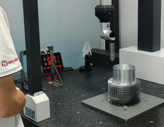
Step 6: In-Process and Final Quality Inspection
Quality checks occur during and after machining. Tools like coordinate measuring machines (CMM) measure dimensions to within ±0.001 mm, while surface profilometers assess finish quality (e.g., Ra 0.2–0.8 µm). Non-conforming parts are flagged for rework or rejection.
Step 7: Post-Processing and Surface Finishing
Post-processing enhances part appearance and functionality. Common techniques include deburring to remove sharp edges, anodizing for corrosion resistance (e.g., adding a 10–50 µm oxide layer), electroplating, sandblasting, or polishing to achieve mirror-like finishes (Ra < 0.1 µm).
Key Processes in Precision Machining
Precision machining involves several core processes, each suited to specific applications and part requirements. Below is a detailed explanation of the most common techniques.
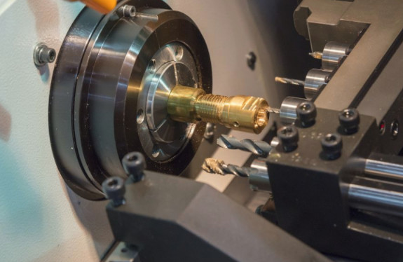
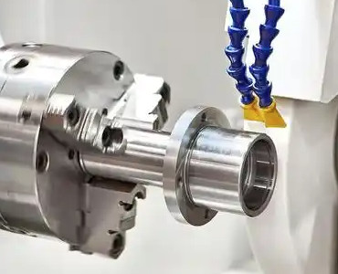
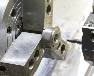
CNC Turning
CNC turning involves rotating a workpiece while a cutting tool removes material to create cylindrical parts, such as shafts, bushings, and fittings. Modern CNC lathes are equipped with multi-axis capabilities, allowing for complex geometries like tapers and threads. Typical parameters include:
- Spindle speed: 500–5000 RPM, depending on material and tool
- Feed rate: 0.05–0.5 mm/rev
- Depth of cut: 0.1–3 mm
Materials commonly used in turning include aluminum, stainless steel, and titanium.
CNC Milling
CNC milling uses rotating cutting tools to remove material from a stationary workpiece, producing flat surfaces, slots, and complex 3D contours. Vertical and horizontal milling machines are employed, with 3-axis, 4-axis, or 5-axis configurations for intricate parts. Key parameters include:
- Cutting speed: 50–300 m/min
- Feed rate: 0.01–0.3 mm/tooth
- Tool diameter: 2–20 mm for precision applications
Milling is versatile, handling materials from soft plastics to hardened steels.
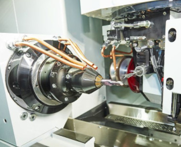
Grinding
Grinding uses abrasive wheels to achieve ultra-smooth surface finishes and tight tolerances, often for finishing operations. Surface, cylindrical, and centerless grinding are common variants. Typical specifications include:
- Surface finish: Ra 0.1–0.4 µm
- Tolerance: ±0.0005 inches (±0.0127 mm)
- Wheel speed: 20–40 m/s
Grinding is ideal for hardened materials like tool steel and ceramics.
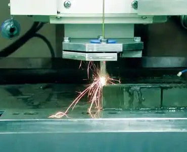
Electrical Discharge Machining (EDM)
EDM uses electrical sparks to erode material from a workpiece, suitable for hard metals and complex shapes. Wire EDM and sinker EDM are widely used. Parameters include:
- Voltage: 50–300 V
- Current: 0.5–400 A
- Surface finish: Ra 0.1–3.2 µm
EDM excels in producing intricate features like micro-holes and cavities.
Tools and Equipment
Precision machining relies on advanced tools and equipment to achieve desired results. The following table summarizes key tools and their applications:
| Tool Type | Application | Material | Typical Specifications |
|---|---|---|---|
| Carbide End Mills | Milling slots, pockets, contours | Steel, aluminum, titanium | Diameter: 1–25 mm, Flutes: 2–6 |
| High-Speed Steel Drills | Drilling holes | Brass, stainless steel, plastics | Diameter: 0.5–50 mm, Point angle: 118°–135° |
| Diamond Grinding Wheels | Finishing hard materials | Ceramics, carbides | Grit size: 100–1200 |
| Wire EDM Electrodes | Cutting intricate shapes | Hardened steel, titanium | Wire diameter: 0.1–0.3 mm |
Tool selection and parameters determine chip formation, heat generation, and tool life. Coated micrograin carbide suits most metals, uncoated polished carbide for aluminum, CBN/ceramic for hardened steels, and PCD for abrasive nonferrous materials and composites.
Geometry includes positive rake angles to lower cutting forces and relief angles of 6–12° for carbide end mills to prevent rubbing. Helix angles range from 35–45° for general milling, 45–55° for aluminum, with variable helix to reduce chatter. Nose radii on turning inserts are 0.4–0.8 mm to balance strength and finish, matched to feed rates to minimize scallops. Depths of cut maintain chip thickness in efficient ranges, avoiding light engagements that cause rubbing. Coolant delivery targets the shear zone, with high-pressure through-tool for deep holes and superalloys.
Typical parameters vary by material and operation. For aluminum 6061-T6 milling: uncoated carbide, vc 300–800 m/min, fz 0.05–0.25 mm/tooth. Turning: carbide, vc 400–1000 m/min, f 0.10–0.40 mm/rev. For steel 4140 at 30–35 HRC milling: TiAlN carbide, vc 120–220 m/min, fz 0.03–0.15 mm/tooth. Turning: coated carbide, vc 150–250 m/min, f 0.10–0.30 mm/rev. Hardened steel at 55 HRC turning: CBN, vc 80–150 m/min, f 0.05–0.20 mm/rev. Titanium Ti-6Al-4V milling: TiAlN carbide, vc 40–90 m/min, fz 0.03–0.10 mm/tooth. Nickel superalloy turning: carbide, vc 30–70 m/min, f 0.05–0.20 mm/rev. Brass milling: carbide, vc 200–400 m/min, fz 0.05–0.18 mm/tooth. POM milling: sharp carbide, vc 300–600 m/min, fz 0.05–0.20 mm/tooth.
Depth guidance for rough milling in steels: ap 0.5–1.5 × D, ae 0.1–0.4 × D. Finishing: ap 0.05–0.2 × D, ae 0.02–0.1 × D. In turning, roughing depth 1.5–4.0 mm, finishing 0.2–0.6 mm with feed less than insert nose radius.
Material Selection
Material choice is critical in precision machining, as it affects machinability, tool life, and part performance. Common materials include:
- Aluminum: Lightweight, corrosion-resistant, easy to machine. Grades like 6061 and 7075 are popular for aerospace components.
- Stainless Steel: Strong, corrosion-resistant, used in medical and food-grade applications. Common grades include 304 and 316.
- Titanium: High strength-to-weight ratio, biocompatible, used in aerospace and medical implants. Grade 5 (Ti-6Al-4V) is prevalent.
- Engineering Plastics: PEEK and Delrin offer low weight and chemical resistance for specialized applications.
- Tool Steel: Hardened for dies and molds, requires grinding or EDM for precision.
- High-temperature alloys: Often called superalloys materials, primarily nickel-based (e.g., Inconel 718, Hastelloy), cobalt-based, or iron-based alloys, offer exceptional strength, heat resistance (up to 1000°C+), and corrosion resistance.
Material properties, such as hardness (e.g., Rockwell C 20–60) and thermal conductivity, dictate machining parameters like cutting speed and coolant use.
Surface Finish
Surface finish influences friction, sealing, fatigue life, and coating adhesion. Roughness parameters include Ra for average roughness, Rz for peak-to-valley height, and when relevant, Rsk for skewness and Rku for kurtosis to describe texture shape. Filtering uses standardized cutoff lengths, such as 0.8 mm for roughness separation from waviness, with settings documented on drawings.
Surface integrity avoids tensile residual stresses, white layers, or thermal damage, verified through etching, hardness testing, or X-ray diffraction if required. Processes like grinding achieve Ra 0.05–0.4 µm, while lapping reaches 0.01–0.05 µm. Measurement targets specify parameters matching function and metrology capability.
Processes achieve specific roughness and tolerances. Rough milling yields Ra 3.2–6.3 µm and ±0.10–0.30 mm for stock removal. Finish milling: Ra 0.8–1.6 µm, ±0.02–0.10 mm for functional faces. Reaming: Ra 0.4–1.0 µm, H7–H9 fits for precision holes. Finish turning: Ra 0.8–1.6 µm, ±0.01–0.05 mm for shafts. Honing: Ra 0.1–0.4 µm, ±0.005–0.015 mm for bores. Grinding: Ra 0.05–0.4 µm, ±0.002–0.01 mm for bearing fits. Lapping: Ra 0.01–0.05 µm, ±0.001–0.005 mm for sealing faces.
Tolerances and Quality Control
Achieving tight tolerances is a hallmark of precision machining. Tolerances vary by process and application, as shown in the table below:
| Process | Tolerance Range | Surface Finish (Ra) |
|---|---|---|
| CNC Turning | ±0.0005–0.005 inches (±0.0127–0.127 mm) | 0.4–1.6 µm |
| CNC Milling | ±0.001–0.005 inches (±0.0254–0.127 mm) | 0.8–3.2 µm |
| Grinding | ±0.0001–0.0005 inches (±0.00254–0.0127 mm) | 0.1–0.4 µm |
| EDM | ±0.0002–0.001 inches (±0.00508–0.0254 mm) | 0.1–3.2 µm |
Quality control involves metrology tools like coordinate measuring machines (CMM), calipers, and surface profilometers to verify dimensions and finishes. Inspection protocols ensure compliance with standards like ISO 9001.
Dimensional tolerances must align with functional fit, assembly stack-ups, and process capabilities. General tolerances follow standards like ISO 2768 for non-critical features, with explicit limits for critical dimensions. GD&T application controls geometric variations efficiently, using datums for reference and modifiers like maximum material condition (MMC) or least material condition (LMC) to optimize allowable variation.
Practical guidance includes selecting stable, orthogonal datums aligned with functional interfaces to minimize shifts across operations. Tolerance zoning tightens specifications only where function demands, aligning process steps to the tightest features. Positional tolerance employs true position with MMC/LMC for functional gaging. Runout controls apply circular runout for rotating features and total runout for axial cumulative errors. Straightness and flatness are managed by controlling base surfaces first, with finishing passes and stress relief to reduce distortion.
Verification uses calibrated equipment and controlled methods with documented criteria. Systems include hand tools like micrometers and calipers for general dimensions, comparators and stylus testers for profiles and roughness, CMMs for tight tolerances with proper probing, and roundness instruments for form and runout.
Quality controls involve measurement system analysis (MSA) with gauge R&R within acceptable variation percentages, plus bias and linearity studies. Statistical process control (SPC) uses charts on critical features, ensuring Cp and Cpk meet goals. Documentation includes ballooned drawings, inspection plans, traceable records, and first article reports. Environmental control measures at 20°C with part stabilization time.
Costing and Validation
Cost and lead time depend on material machinability, tolerance levels, surface requirements, and setup count. Design guidelines rationalize tolerances using general standards where possible, limiting tight ones to functional needs. Feature simplification prefers standard radii and chamfers, avoiding deep narrow slots. Wall thickness maintains consistency to reduce distortion, adding ribs for stiffness. Holes and threads standardize sizes with reliefs and adequate depths. Setup minimization ensures datum faces accessible in one clamping, combining features in common orientations.
Validation confirms capability through trials and measurements before production. Controls include run-at-rate production for stability verification. Control plans define characteristics, methods, frequencies, and reaction plans. Tool life management sets counters by time-in-cut or material length, using wear offsets and scheduled changes. Change management documents parameter, tool, or routing alterations with assessments and re-approvals.
Worked examples
Parameter derivations align spindle speed, feed, and engagement with material and tool data to hit tolerance and finish targets.
Example 1: Milling aluminum with a 10 mm end mill
Tool: 2- or 3-flute carbide, polished/ZrN-coated, 45° helix.
Speed: 6000–12,000 RPM (cutting speed 200–300 m/min).
Feed: 1200–3600 mm/min (chip load 0.05–0.15 mm/tooth).
Depth: 5–15 mm axial, 1–3 mm radial (10–30% for side cuts).
Tips: Use climb milling, flood/mist coolant, secure workholding, ensure chip evacuation.
Example 2: Turning 4140 (32 HRC) to size
Tool: Carbide insert (CNMG/WNMG, P20–P30, TiAlN-coated).
Speed: 80–120 m/min (~640 RPM for 50 mm diameter).
Feed: 0.15–0.3 mm/rev.
Depth: 0.5–2 mm.
Tips: Use coolant, rigid setup, neutral/positive rake.
Applications of Precision Machining
Precision machining serves industries requiring high-accuracy components:
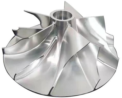
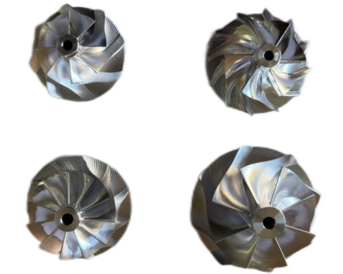
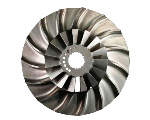
- Aerospace: Turbine blades, landing gear components, and structural fittings with tolerances of ±0.0005 inches (±0.0127 mm).
- Automotive: Engine parts, transmission gears, and fuel injectors requiring smooth finishes (Ra 0.8 µm).
- Medical: Surgical instruments, implants, and prosthetics made from biocompatible materials like titanium.
- Electronics: Micro-components like connectors and housings with intricate geometries.
Precision Machining with Kesu
- Micron-level accuracy for complex components, meeting exact specifications.
- Advanced CNC technology and skilled engineers ensure consistent quality.
- Customized and comprehensive services, from prototyping to high-volume production.
In CNC precision machining Kesu is among the top manufacturer of machine parts all over the world and in China we are the top 5 best service providers of CNC precision machining parts.
FAQ
What is precision machining?
Precision machining is a subtractive manufacturing process that removes material from a workpiece to create parts with tight tolerances and high accuracy, typically using CNC machines.
What materials are used in precision machining?
Common materials include aluminum, stainless steel, titanium, engineering plastics (e.g., PEEK), and tool steel, selected based on machinability and application requirements.
What are typical tolerances in precision machining?
Tolerances range from ±0.0001 inches (±0.00254 mm) for grinding to ±0.005 inches (±0.127 mm) for milling, depending on the process and application.