
Propellers are rotating devices that convert rotational energy into linear thrust, propelling vehicles through fluids like water or air. Found in ships, aircraft, and industrial systems, propellers rely on complex blade designs to optimize efficiency, thrust, and durability. This guide examines the structure of propellers, their diverse applications, and the machining processes used in their manufacture. Detailed technical parameters and practical insights provide a foundation for understanding their design and production, catering to marine, aviation, and industrial contexts. The focus remains on technical accuracy and applicability, drawing from established engineering principles.
Understanding Propellers
A propeller consists of a central hub and radiating blades, shaped to form a helical spiral that generates thrust by creating a pressure difference in the fluid, per Bernoulli’s principle and Newton’s third law. The blades’ rotational motion accelerates fluid backward, producing forward thrust. Propellers vary in size, material, and design, tailored to specific applications like marine propulsion or aircraft lift. Their efficiency depends on factors like blade shape, pitch, and rotational speed.
Basic Operating Principles
Propellers operate by rotating blades at a specific pitch, creating a pressure differential between the blade’s forward and aft surfaces. In marine propellers, this thrust drives a vessel through water; in aircraft, it generates lift or forward motion. Key parameters include:
- Blade Pitch: The distance a propeller would travel in one revolution, typically 0.5–2.5 m for marine propellers and 0.3–1.5 m for aircraft propellers.
- Rotational Speed: 100–2000 RPM for ships, 1000–3000 RPM for aircraft.
- Diameter: 0.5–10 m for marine propellers, 1–4 m for aircraft propellers.
The efficiency of a propeller, often 70–85% for well-designed systems, depends on minimizing cavitation (in water) or drag (in air).
Types of Propellers
Propellers are classified by their design and application. Common types include:
- Fixed Pitch Propellers (FPP): Blades are cast in a fixed position, offering simplicity and durability for consistent operating conditions.
- Controllable Pitch Propellers (CPP): Blades rotate about their axis to adjust pitch, improving maneuverability but requiring complex hydraulic systems.
- Cleaver Propellers: High-speed, surface-piercing designs for lightweight vessels, with pitch angles of 20–30°.
- Twisted-Toroid Propellers: Ring-shaped designs that reduce noise and improve efficiency by 5–10% over traditional blades.
Each type suits specific fluid dynamics and operational needs, influencing material and machining choices.
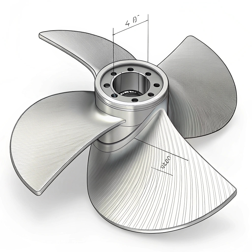
Propeller Structure
The structure of a propeller comprises a hub, blades, and sometimes additional features like boss cap fins or leading-edge protections. The design balances aerodynamic or hydrodynamic performance with structural integrity, accounting for fluid density, operational loads, and environmental conditions.
Hub Design
The hub connects the propeller to the drive shaft, transmitting torque and supporting the blades. It is typically cylindrical, with a tapered bore for marine propellers or a flanged mount for aircraft. Specifications include:
- Hub Diameter: 10–30% of propeller diameter (e.g., 0.1–3 m).
- Material: Cast steel, bronze, or aluminum alloys for marine; forged aluminum for aircraft.
- Bore Tolerance: ±0.001 mm for precise shaft alignment.
The hub may include keyways or splines for torque transfer and is designed to minimize stress concentrations.
Blade Design
Blades are the primary thrust-generating components, shaped as airfoils or hydrofoils with varying twist and chord length. The blade’s geometry is defined by:
- Chord Length: 0.1–1 m, widest at 70–80% of the radius.
- Twist Angle: 10–45°, optimized for uniform lift distribution.
- Thickness: 5–20% of chord length, thicker at the root for strength.
Blades are designed using computational fluid dynamics (CFD) to maximize lift-to-drag ratio, with features like tip rakes or serrations to reduce noise and cavitation.
Additional Features
Modern propellers incorporate enhancements like:
- Boss Cap Fins: Reduce hub vortex losses, improving efficiency by 2–5%.
- Leading-Edge Protection: Polyurethane or nickel alloys (e.g., Hercuthane) to resist erosion.
- Shear Pins: In small engines (<10 hp), designed to fail under overload to protect the drivetrain.
These features enhance durability and performance in harsh environments.
Materials for Propellers
Propeller materials are chosen for strength, corrosion resistance, and machinability. Common materials include metals, composites, and wood laminates, each suited to specific applications.
Metals and Alloys
Marine propellers often use copper alloys (e.g., manganese bronze, nickel-aluminum bronze) or stainless steel, while aircraft propellers favor aluminum or titanium. Properties include:
- Tensile Strength: 500–800 MPa for bronze, 900–1200 MPa for stainless steel.
- Corrosion Resistance: Nickel-aluminum bronze withstands seawater for 10–15 years.
- Density: 2.7 g/cm³ for aluminum, 8.4 g/cm³ for bronze.
Inconel, a nickel-chromium superalloy, is used for high-performance marine applications due to its oxidation resistance.
Composites and Wood
Composite propellers, using carbon or aramid fibers with epoxy resin, offer weight savings and vibration damping. Wood laminates, like hydulignum, are used in vintage aircraft. Specifications include:
- Composite Tensile Strength: 1–2 GPa.
- Wood Density: 0.6–0.8 g/cm³ for laminates.
- Resin Transfer Molding (RTM) Cycle Time: 30–60 minutes for composite blades.
Composites reduce weight by 20–30% compared to metal, enhancing fuel efficiency.
Applications of Propellers
Propellers are integral to marine, aviation, and industrial systems, each requiring specific designs to meet performance goals like speed, efficiency, or thrust.
Marine Applications
Marine propellers propel vessels from small boats to large tankers. They operate in dense water (1000 times denser than air), requiring robust designs. Parameters include:
- Thrust: 10–1000 kN for commercial ships.
- Blade Number: 3–7, balancing efficiency and vibration.
- Applications: Cargo ships, yachts, and naval vessels.
Propellers must resist cavitation, which can erode blades, reducing efficiency by 5–10%.
Aviation Applications
Aircraft propellers, used in piston-engine planes and turboprops, generate thrust or lift. They require lightweight materials and precise blade shapes. Specifications include:
- Power Output: 50–2000 hp.
- Blade Length: 0.5–2 m.
- Applications: General aviation, cargo planes, and drones.
Composite blades, like the ASC-II, reduce weight and improve efficiency for planes like the Cirrus SR-22.
Industrial and Other Applications
Propellers are used in industrial fans, wind turbines, and water pumps. Industrial fans require large diameters (1–5 m) and low speeds (50–500 RPM). Wind turbine blades, though similar, are optimized for energy capture rather than thrust.
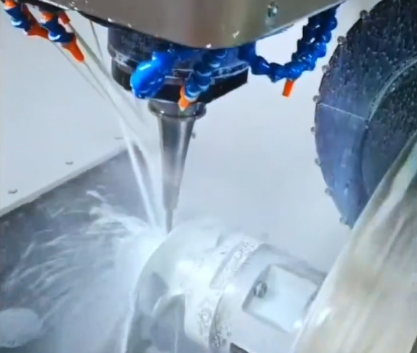
Machining Processes for Propellers
Machining propellers involves precision techniques to achieve complex geometries, tight tolerances, and smooth surfaces. Computer numerical control (CNC) machining dominates, with processes tailored to material and application.
CNC Machining Techniques
CNC machining uses 3- to 5-axis machines to mill propeller blades and hubs from castings, forgings, or billets. Key techniques include:
- Roughing: Removes excess material (0.5–5 mm) using flat-end cutters at 100–500 mm/min feed rates.
- Finishing: Uses ball-end or cylindrical milling cutters for surface finish (Ra 0.4–1.6 µm).
- Blade Root Machining: Ball-end cutters create fillets with radii of 5–20 mm.
Five-axis CNC machines are preferred for complex blade surfaces, achieving tolerances of ±0.01 mm.
Fixturing and Tooling
Fixturing ensures stability during machining. Common setups include:
- Clamp-and-Support: Clamps on the hub with tailstock support for blades.
- Fixture Plates: Aluminum plates (e.g., 8.4-inch square, 1-inch thick) with hole patterns for clamping.
- Vibration Control: Nested supports under blades reduce chatter at depths of cut (0.1–1 mm).
Tooling includes carbide or high-speed steel cutters, with diameters of 5–50 mm.
Challenges and Solutions
Machining propellers presents challenges like:
- Complex Geometry: Free-form surfaces require multi-axis machining and CAD/CAM integration.
- Material Deformation: Casting shrinkage (1–2%) necessitates adaptive machining paths.
- Surface Finish: Hand-finishing (2–10 hours) is often needed to achieve Ra 0.4 µm.
Solutions include laser-vision sensors for real-time compensation and robotic grinding for edge sharpening.
Quality Control and Testing
Quality control ensures propellers meet design specifications. Non-destructive testing (NDT) and performance evaluations are standard.
- Ultrasonic Inspection: Detects internal defects in castings.
- Coordinate Measuring Machines (CMM): Verify blade geometry to ±0.01 mm.
- Balancing: Ensures vibration-free operation at 360° rotation, targeting <0.1 g imbalance.
Testing includes hydrodynamic or aerodynamic trials to measure thrust, efficiency, and cavitation.
Frequently Asked Questions
What materials are most common for propellers?
Marine propellers use bronze, stainless steel, or nickel alloys, while aircraft propellers favor aluminum or composites. Wood laminates are used in vintage aircraft.
How does blade pitch affect propeller performance?
Higher pitch increases thrust but requires more power, while lower pitch improves efficiency at lower speeds. Optimal pitch depends on the application.
What is the advantage of CNC machining for propellers?
CNC machining offers precision (±0.01 mm), repeatability, and the ability to handle complex geometries, reducing hand-finishing time.
What are common machining challenges?
Challenges include complex blade surfaces, casting deformations, and vibration during machining, addressed by multi-axis CNC and adaptive toolpaths.
How is propeller efficiency measured?
Efficiency is measured as the ratio of useful thrust power to input power, typically 70–85% for marine and aircraft propellers.