Shaft machining is a critical manufacturing process that produces cylindrical components essential for transmitting power, torque, and motion in machinery. This guide provides a detailed overview of the types of shafts, materials used, prototyping considerations, and the complexities involved in achieving high precision during processing.
Overview of Shaft Machining
Shaft machining involves shaping cylindrical components, often referred to as axles, rods, or spindles, to meet specific dimensional and functional requirements. These components are integral to industries such as automotive, aerospace, and industrial machinery, where they facilitate power transmission and rotational motion. The process typically involves subtractive manufacturing techniques, where material is removed from a workpiece to achieve the desired shape, size, and surface finish. Achieving tight tolerances, typically ranging from ±0.01 mm to ±0.05 mm for diameter and ±0.1 mm to ±0.2 mm for length, is essential for ensuring proper fit and performance in assemblies. The machining process requires careful selection of tools, materials, and techniques to address challenges like tool wear, thermal expansion, and dimensional accuracy.
Types of Shafts and Their Machining Processes
Shafts come in various designs, each tailored to specific applications and requiring distinct machining approaches. Below is a detailed explanation of common shaft types and the processes used to manufacture them.
Straight Shafts
Straight shafts are simple cylindrical components used to transmit power between machine elements, such as motors and gears. They are typically machined using CNC turning, where the workpiece rotates while a stationary cutting tool removes material. This process achieves tight tolerances (e.g., ±0.02 mm for diameter) and smooth surface finishes, often with a roughness average (Ra) of 0.8–1.6 µm. CNC turning is efficient for producing long, uniform shafts and can incorporate features like keyways or grooves through additional milling operations.
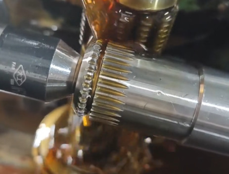
Splined Shafts
Splined shafts feature teeth or ridges on their surface to transmit high torque to mating components with matching grooves, commonly used in automotive drivetrains. Machining splined shafts often involves CNC milling for external splines, using multi-point cutters to create precise involute or straight-sided profiles. For internal splines, broaching is preferred, where a toothed tool removes material in a single pass, ensuring repeatability and a surface finish of Ra 0.4–0.8 µm. Spline machining requires high precision to maintain alignment and torque capacity, with tolerances as tight as ±0.015 mm for spline dimensions.
Threaded Shafts
Threaded shafts, used for converting rotational motion to linear motion (e.g., lead screws in CNC machines), feature spiral ridges machined through threading processes. CNC lathes equipped with threading tools or thread mills create threads with pitches ranging from 0.5 mm to 2.0 mm, adhering to standards like ISO 68-1. Thread milling is preferred for deep threads due to better chip evacuation, maintaining tolerances of ±0.025 mm for thread depth and pitch accuracy. Surface finishes typically achieve Ra 0.8–1.2 µm to ensure smooth operation.
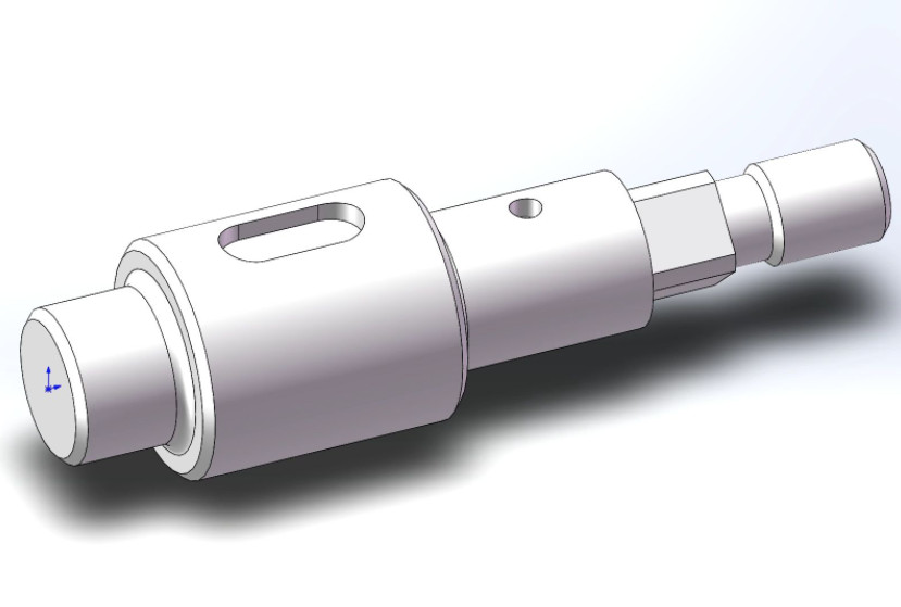
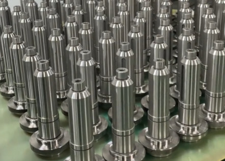
Stepped Shafts
Stepped shafts have varying diameters along their length, used in applications requiring multiple bearing surfaces or component mounting. CNC turning is the primary method, with tools programmed to create precise transitions between diameters. Tolerances for stepped features are typically ±0.03 mm, and surface finishes range from Ra 0.8–1.6 µm. Additional milling or grinding may be required for features like flats or slots, increasing process complexity.
Materials for Shaft Machining
Material selection is critical in shaft machining, as it affects strength, durability, and machinability. The table below summarizes common materials and their properties relevant to shaft production.
| Material | Properties | Applications | Machinability Considerations |
|---|---|---|---|
| Carbon Steel (e.g., AISI 1045) | High strength, good machinability, cost-effective | General-purpose shafts, automotive components | Moderate tool wear, requires coolant to manage heat |
| Stainless Steel (e.g., 304, 316) | Corrosion resistance, high durability | Marine, medical, food processing equipment | Higher tool wear, lower thermal conductivity |
| Aluminum (e.g., 6061-T6) | Lightweight, corrosion-resistant, easy to machine | Aerospace, lightweight machinery | Prone to burr formation, requires sharp tools |
| Titanium (e.g., Ti-6Al-4V) | High strength-to-weight ratio, corrosion-resistant | Aerospace, biomedical implants | Difficult to machine, high tool wear, low thermal conductivity |
Material choice depends on factors like load capacity, environmental conditions, and cost. For example, carbon steel is widely used for its balance of strength and affordability, while titanium is selected for high-performance applications despite its machining challenges. Heat treatment processes, such as carburizing or quenching, are often applied post-machining to enhance hardness (e.g., 58–62 HRC for carburized steel) and wear resistance.
Prototyping in Shaft Machining
Prototyping is a crucial step in shaft machining to validate designs before full-scale production. Prototypes allow engineers to test dimensional accuracy, material performance, and functional compatibility. CNC machining is commonly used for prototyping due to its flexibility and precision, enabling rapid production of small batches. For complex shafts, such as those with splines or threads, 3D modeling software (e.g., SolidWorks, Fusion 360) is used to create detailed designs, which are then translated into G-code for CNC machines. Prototyping often involves softer materials like aluminum to reduce costs and machining time, with tolerances relaxed to ±0.1 mm for initial testing. Iterative testing during prototyping helps identify issues like misalignment or inadequate surface finish, which can be corrected before final production.
Difficulties in Shaft Machining
Shaft machining presents several challenges that impact quality, cost, and production efficiency. Below are the primary difficulties encountered, with a focus on precision, complexity, and processing challenges.
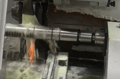
Precision Requirements
Achieving high precision is a significant challenge in shaft machining, as many applications require tolerances as tight as ±0.01 mm for critical dimensions like diameter and concentricity. Factors such as tool deflection, machine vibration, and thermal expansion can introduce errors. For example, during high-speed turning, heat generation can cause the workpiece to expand by 0.01–0.02 mm, affecting dimensional accuracy. Advanced CNC machines with thermal compensation and in-process measurement systems are often required to maintain precision. Additionally, surface finish requirements (e.g., Ra 0.4 µm for bearing surfaces) necessitate fine grinding or polishing, adding time and cost to the process.
Complexity of Features
Shafts with complex features, such as splines, threads, or stepped profiles, increase machining difficulty. For instance, machining involute splines requires precise tool alignment and multiple passes to achieve the correct tooth geometry, with errors as small as 0.02 mm potentially causing torque transmission issues. Threaded shafts demand consistent pitch and depth, requiring specialized tools and setups. Multi-axis CNC machines (e.g., 5-axis milling) are often needed for complex geometries, increasing setup time and programming complexity. These factors can extend production cycles and require skilled operators to ensure accuracy.
Material-Related Challenges
Hard-to-machine materials like titanium and stainless steel pose significant difficulties due to their high strength and low thermal conductivity. Titanium, for example, generates high cutting forces, leading to tool wear rates up to 50% higher than for carbon steel. This necessitates frequent tool changes and the use of carbide or diamond-coated tools, increasing costs. Additionally, materials like aluminum are prone to burr formation, requiring secondary deburring processes to achieve a smooth finish. Coolant selection and chip management are critical to prevent work hardening and tool damage during machining.
Tool Wear and Machine Limitations
Tool wear is a persistent issue in shaft machining, particularly for high-volume production or hard materials. For example, machining stainless steel with carbide tools can result in tool life reduction after 20–30 minutes of continuous cutting. Worn tools lead to dimensional inaccuracies and poor surface finishes, necessitating frequent tool inspections and replacements. Machine limitations, such as spindle runout (typically 0.005–0.01 mm) or insufficient rigidity, can also compromise precision, especially for long shafts where deflection becomes a concern.
Strategies to Overcome Machining Difficulties
To address the challenges in shaft machining, manufacturers employ several strategies. Using advanced CNC machines with high spindle speeds (e.g., 10,000–20,000 RPM) and rigid setups minimizes vibration and improves precision. In-process monitoring systems, such as laser gauges, ensure real-time dimensional accuracy within ±0.005 mm. For complex features, multi-axis machining centers reduce setup changes and improve repeatability. Optimizing cutting parameters, such as feed rates (0.1–0.3 mm/rev) and cutting speeds (100–300 m/min), balances tool life and productivity. Additionally, selecting appropriate coolants, like water-based emulsions for aluminum or oil-based for titanium, reduces thermal effects and tool wear.
Quality Control in Shaft Machining
Quality control is essential to ensure shafts meet design specifications. Common inspection methods include coordinate measuring machines (CMM) for dimensional accuracy, achieving measurement resolutions of 0.001 mm, and surface profilometers for assessing finish (Ra 0.4–1.6 µm). For critical applications, non-destructive testing (e.g., ultrasonic or magnetic particle inspection) detects subsurface defects. Statistical process control (SPC) monitors production consistency, using control charts to track variations in diameter or concentricity. These methods ensure compliance with standards like ISO 9001 and reduce the risk of defective components reaching assembly.