Aero-engine turbine blades are critical components that operate under extreme conditions, including high temperatures, pressures, and rotational speeds. The machining of these blades requires exceptional precision due to their complex geometries and the stringent performance requirements of aerospace applications. However, deformation during machining remains a significant issue that can compromise dimensional accuracy and surface integrity. This article provides a systematic approach to addressing deformation in turbine blade machining, focusing on causes, solutions, and technical parameters to ensure high-quality production.
Understanding Deformation in Turbine Blade Machining
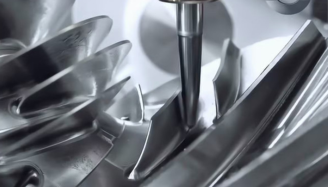
Deformation in turbine blade machining refers to unintended changes in the blade's geometry during or after the manufacturing process. These changes can result from mechanical, thermal, or material-related factors. Turbine blades, typically made from nickel-based superalloys or titanium alloys, are prone to deformation due to their thin, complex profiles and the high stresses involved in machining. For instance, blades often have airfoil shapes with thicknesses as low as 0.5 mm in certain sections, making them susceptible to distortion under cutting forces.
The primary types of deformation include elastic deformation, plastic deformation, and residual stress-induced distortion. Elastic deformation is temporary and reversible, occurring during machining due to cutting forces. Plastic deformation is permanent and results from excessive forces or heat exceeding the material’s yield strength. Residual stress-induced distortion manifests after machining, as internal stresses relax and cause warping. Addressing these issues requires a thorough understanding of the machining process and material behavior.
Key Causes of Deformation
Identifying the root causes of deformation is essential for developing effective solutions. The following factors contribute significantly to deformation in turbine blade machining:
- Material Properties: Nickel-based superalloys, such as Inconel 718, have high strength and low thermal conductivity, leading to localized heat buildup during machining. This can cause thermal expansion and subsequent deformation. For example, Inconel 718 has a thermal conductivity of approximately 11.4 W/m·K at room temperature, compared to 237 W/m·K for aluminum.
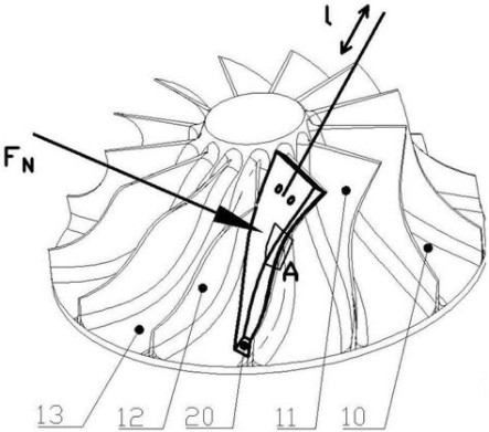
- Cutting Forces: High cutting forces, particularly in rough machining, can deflect thin blade sections. For a typical milling operation, cutting forces may range from 500 N to 2000 N, depending on tool geometry and machining parameters.
- Thermal Effects: Heat generated during machining, especially in high-speed processes, can cause thermal gradients. A temperature rise of 300°C in the cutting zone can induce thermal stresses exceeding 500 MPa in nickel-based alloys.
- Clamping and Fixturing: Improper clamping can introduce initial stresses or uneven force distribution. For instance, excessive clamping pressure (e.g., 10 MPa) on a thin blade section can cause local deformation.
- Residual Stresses: Machining processes like milling or grinding introduce residual stresses, typically in the range of 200–800 MPa, which can lead to distortion upon unclamping.
- Tool Wear: Worn tools increase cutting forces and heat generation. A tool with flank wear of 0.2 mm can increase cutting forces by up to 30%.
Solutions to Mitigate Deformation
Controlling deformation requires a combination of optimized machining parameters, advanced tooling, and precise fixturing. The following solutions are derived from industry practices and technical research, ensuring reliability and effectiveness.
Optimized Machining Parameters
Adjusting machining parameters is a primary method for reducing deformation. Key parameters include cutting speed, feed rate, depth of cut, and coolant application. For nickel-based superalloys, the following parameters are recommended:
| Parameter | Recommended Range | Effect on Deformation |
|---|---|---|
| Cutting Speed | 20–50 m/min | Lower speeds reduce heat generation, minimizing thermal deformation. |
| Feed Rate | 0.05–0.15 mm/tooth | Moderate feed rates balance cutting forces and heat buildup. |
| Depth of Cut | 0.1–0.5 mm | Shallow cuts reduce cutting forces and residual stresses. |
| Coolant Pressure | 50–100 bar | High-pressure coolant dissipates heat, reducing thermal gradients. |
These parameters should be tailored to the specific material and blade geometry. For example, a lower cutting speed (20 m/min) is preferred for thin-walled sections to minimize heat input.
Advanced Tooling and Tool Path Strategies
Tool selection and path planning play a critical role in deformation control. Tools with high rigidity and wear-resistant coatings, such as TiAlN or AlCrN, are recommended for machining superalloys. A tool diameter of 8–12 mm with 4–6 flutes ensures stability and efficient chip evacuation. Tool overhang should be limited to 3–4 times the tool diameter to reduce deflection.
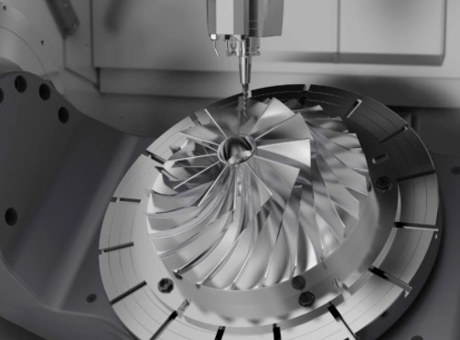
Tool path strategies, such as trochoidal milling or adaptive milling, distribute cutting forces evenly and reduce heat concentration. For instance, trochoidal milling maintains a constant chip thickness of 0.1 mm, reducing forces by up to 20% compared to conventional milling. Additionally, using 5-axis CNC machines allows for smoother tool paths and better access to complex geometries, minimizing stress concentrations.
Improved Clamping and Fixturing
Effective fixturing minimizes initial stresses and supports the blade during machining. Vacuum fixtures or low-pressure clamping systems (e.g., 2–5 MPa) are ideal for thin blades. For a blade with a length of 100 mm and thickness of 1 mm, a distributed clamping force along the blade’s length reduces deflection by up to 50%. Additionally, using compliant fixtures that adapt to the blade’s geometry can further mitigate deformation.
Simulation tools, such as finite element analysis (FEA), can optimize fixture design. For example, an FEA model can predict clamping-induced stresses, ensuring they remain below 100 MPa to avoid plastic deformation.
Thermal Management
Controlling thermal effects is crucial for deformation prevention. High-pressure coolant systems, operating at 50–100 bar, effectively remove heat from the cutting zone. Minimum quantity lubrication (MQL) with oil mist at 0.5–1 ml/h can also reduce thermal deformation while maintaining tool life. For high-speed machining, cryogenic cooling using liquid nitrogen at -195°C has shown to reduce cutting temperatures by 40%, significantly lowering thermal stresses.
Post-Machining Stress Relief
Residual stresses can be mitigated through post-machining treatments. Heat treatment at 650°C for 4 hours in a vacuum furnace can reduce residual stresses in nickel-based alloys by 60–80%. Alternatively, vibratory stress relief at a frequency of 50–100 Hz for 30 minutes can achieve similar results without altering material properties. These treatments should be applied before final inspection to ensure dimensional stability.

Quality Control and Inspection
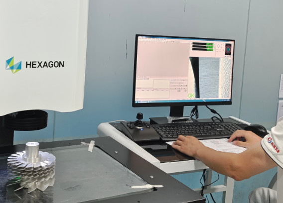
Ensuring deformation-free blades requires rigorous quality control. Coordinate measuring machines (CMMs) with a resolution of 0.001 mm are used to verify dimensional accuracy. For a turbine blade with a tolerance of ±0.02 mm, CMM inspection can detect deviations caused by deformation. Non-destructive testing (NDT) methods, such as X-ray computed tomography, can identify internal residual stresses or defects.
In-process monitoring using force sensors or thermal cameras can detect anomalies during machining. For example, a force sensor with a sensitivity of 0.1 N can identify sudden increases in cutting forces, indicating potential deformation risks. These technologies enhance process reliability and reduce scrap rates.
Case Study: Practical Application
In a manufacturing facility producing turbine blades for a high-thrust aero-engine, deformation issues were observed in blades made from Inconel 718. The blades, with a length of 120 mm and minimum thickness of 0.8 mm, exhibited warping of up to 0.05 mm after milling. The following measures were implemented:
- Reduced cutting speed from 60 m/min to 30 m/min, lowering thermal stresses.
- Adopted trochoidal milling with a chip thickness of 0.08 mm, reducing cutting forces by 25%.
- Used a vacuum fixture with a pressure of 3 MPa, minimizing clamping-induced deformation.
- Applied high-pressure coolant at 80 bar, reducing cutting zone temperatures by 30%.
- Performed vibratory stress relief at 80 Hz for 20 minutes, reducing residual stresses by 70%.
Post-implementation, deformation was reduced to within 0.01 mm, meeting the required tolerance of ±0.015 mm. This case demonstrates the effectiveness of a multi-faceted approach to deformation control.
Conclusion
Deformation in aero-engine turbine blade machining is a complex issue driven by material properties, cutting forces, thermal effects, clamping, residual stresses, and tool wear. By optimizing machining parameters, using advanced tooling, improving fixturing, managing thermal effects, and applying stress relief treatments, manufacturers can achieve high precision and reliability. Quality control through advanced inspection and in-process monitoring further ensures compliance with stringent aerospace standards. Implementing these solutions systematically can significantly reduce deformation, enhancing the performance and longevity of turbine blades in aero-engines.