Turbine blades are critical components in gas turbines, steam turbines, and wind turbines, designed to convert energy from fluid flow into mechanical power. These components, also referred to as rotor blades, airfoils, or vanes, operate under extreme conditions, requiring advanced materials and precise manufacturing. This guide provides a detailed examination of turbine blade applications, materials, and machining processes, emphasizing precision, complexity, and manufacturing requirements.
Overview of Turbine Blades
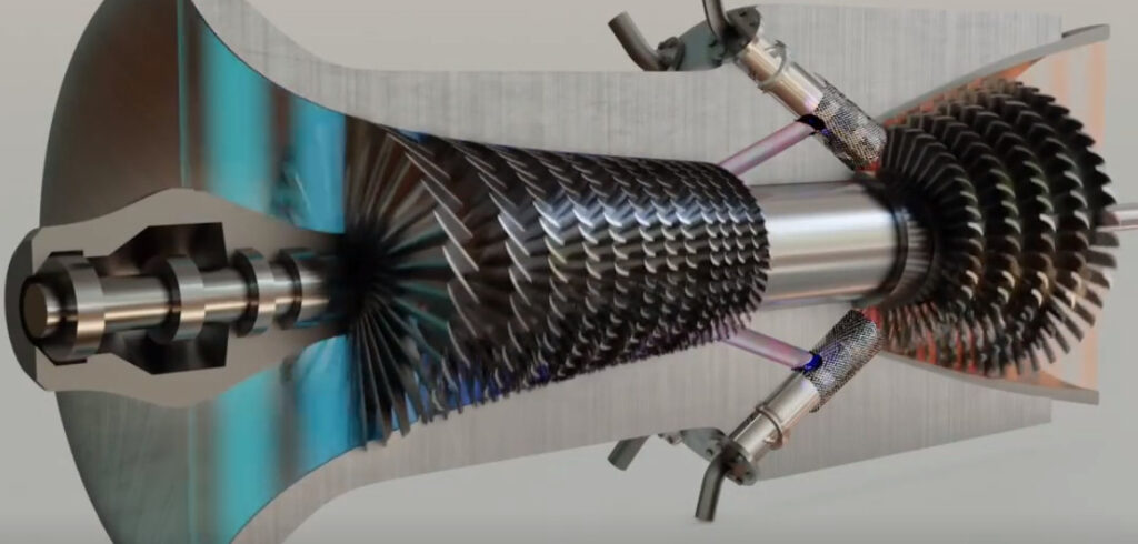
Turbine blades are radial aerofoils mounted on a turbine disc, generating tangential force to rotate the rotor. They extract energy from high-temperature, high-pressure gas in gas turbines, steam in steam turbines, or wind in wind turbines. The design and manufacturing of these components, often called turbine vanes or rotor airfoils, demand high precision due to their complex geometries and operational stresses. Blades must withstand temperatures exceeding 1600°C (2900°F) in aerospace applications and endure mechanical loads from centrifugal forces and vibrations.
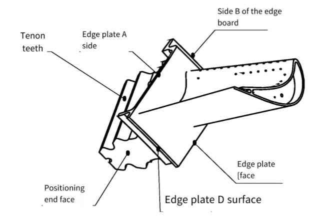
Key components include the airfoil (the aerodynamic surface), root (for mounting to the rotor), and shroud (to reduce vibration). The blade's shape, including curvature and twist, is optimized using computational fluid dynamics (CFD) to ensure efficient energy transfer. Manufacturing processes must maintain tight tolerances, often in the micrometer range, to meet aerodynamic and structural requirements.
Applications of Turbine Blades
Turbine blades are integral to various industries, each with specific requirements for design and performance. Below are the primary applications:
- Aerospace: Turbine blades in jet engines, referred to as aerofoils or compressor blades, operate in high-temperature, high-pressure environments. They are designed to maximize thrust while enduring temperatures up to 1600°C and rotational speeds exceeding 10,000 RPM.
- Power Generation: In steam and gas turbines, blades convert thermal energy into mechanical power for electricity generation. These blades, often called stator vanes or rotor blades, handle steam at 500–600°C and pressures up to 200 bar.
- Wind Turbines: Wind turbine blades, also known as rotor airfoils, capture kinetic energy from wind. These blades, typically 50–100 meters long, are made from lightweight composites to optimize energy capture at wind speeds of 7–65 mph.
- Industrial Applications: Turbine blades are used in turbochargers and marine propulsion systems, requiring durability under cyclic loading and corrosive environments.
Each application demands specific blade designs, such as impulse blades for high-velocity flows or reaction blades for pressure-driven flows, influencing material selection and machining processes.
Materials for Turbine Blades
The choice of materials for turbine blades, also termed turbine vanes or airfoils, is critical to their performance. Materials must withstand high temperatures, mechanical stresses, and environmental factors like corrosion or erosion. Common materials include:
| Material | Properties | Applications |
|---|---|---|
| Nickel-Based Superalloys | High thermal resistance (up to 1100°C), excellent creep strength, corrosion resistance | Jet engines, gas turbines |
| Titanium Alloys | Lightweight, high strength-to-weight ratio, good corrosion resistance | Aerospace compressor blades, low-temperature applications |
| Ceramic Matrix Composites (CMCs) | High thermal resistance (up to 1650°C), lightweight, durable | Advanced jet engines, high-temperature turbines |
| Glass/Carbon Fiber Composites | Lightweight, high fatigue resistance, corrosion-resistant | Wind turbine blades |
Nickel-based superalloys, such as Inconel or René alloys, are commonly used in gas turbines due to their ability to maintain strength at high temperatures. Titanium alloys, like Ti-6Al-4V, are preferred in aerospace for their low density. CMCs are increasingly adopted for their ability to withstand extreme temperatures, while composites are standard for wind turbine blades due to their lightweight properties. Material selection influences machining processes, as harder materials like superalloys require specialized tools and techniques.
Machining Processes for Turbine Blades
Machining turbine blades, also known as rotor vanes or aerofoils, is a complex process due to their intricate geometries, tight tolerances, and challenging materials. The primary machining methods include precision casting, CNC milling, grinding, and additive manufacturing. Below is a detailed examination of these processes, focusing on precision, complexity, and difficulties.
Precision Casting
Precision casting, often referred to as investment casting or lost-wax casting, is the most common method for manufacturing turbine blades. The process involves creating a wax model of the blade, coating it with a ceramic shell, and pouring molten alloy into the mold. For hollow blades, a ceramic core forms internal cooling passages, which is later dissolved. Key parameters include:
- Mold Temperature: 900–1100°C to ensure proper alloy flow.
- Cooling Rate: Controlled at 10–50°C/min for directional solidification to minimize defects.
- Tolerance: ±0.05 mm for airfoil surfaces.
This method is suitable for complex geometries but requires precise control to avoid defects like porosity or inclusions. Post-casting machining is often needed to achieve final dimensions and surface finish.
CNC Milling
Computer Numerical Control (CNC) milling, particularly 5-axis or 9-axis milling, is used for roughing, semi-finishing, and finishing turbine blades. The process removes material from a forged or cast blank to achieve the desired airfoil shape, root geometry, and cooling holes. Key aspects include:
- Tooling: Solid carbide end mills or indexable insert tools (e.g., CoroMill 316) for high material removal rates.
- Feed Rate: 500–900 mm/min for roughing, 100–300 mm/min for finishing.
- Depth of Cut: 0.25–1.0 mm for roughing, 0.025–0.1 mm for finishing.
- Tolerance: ±0.01 mm for critical airfoil surfaces.
The complexity of CNC milling arises from the blade’s thin-walled, twisted geometry, which is prone to vibration and deformation. Toolpath planning using CAD/CAM software (e.g., UG, Hypermill) is critical to avoid collisions or overcuts. Vibration control requires light-cutting tools and dampening systems to maintain precision.
Creep Feed Grinding
Creep feed grinding is used for precision machining of turbine blade roots (e.g., fir-tree contours) and airfoil surfaces. This method employs a continuously dressed grinding wheel to remove material at low feed rates. Parameters include:
- Wheel Speed: 20–30 m/s for consistent material removal.
- Feed Rate: 500–900 mm/min.
- Depth of Cut: 0.025–0.25 mm per pass.
- Tolerance: ±0.005 mm for root profiles.
The process ensures high surface quality but is time-consuming and requires careful control to avoid thermal damage or residual stresses. Cylindrical locators are used to minimize deformation during clamping.
Additive Manufacturing
Additive manufacturing, such as Selective Laser Melting (SLM) or Direct Metal Laser Sintering (DMLS), is used for prototyping or producing complex blades with internal cooling channels. The process builds blades layer by layer using metal powders. Key parameters include:
- Layer Thickness: 20–50 microns for high precision.
- Laser Power: 400 W for melting maraging steel or titanium alloys.
- Scan Speed: 700–1500 mm/s.
- Tolerance: ±0.1 mm, requiring post-machining for critical surfaces.
Additive manufacturing reduces material waste but faces challenges in achieving the required surface finish (Ra 1.6–3.2 µm) and dimensional accuracy, necessitating additional machining.
Precision and Complexity in Machining
Machining turbine blades requires exceptional precision due to their aerodynamic and structural demands. Tolerances as tight as ±0.005 mm are common for airfoil surfaces and root geometries to ensure optimal performance. Complexity arises from:
- Geometry: Twisted, thin-walled airfoils with complex curvatures require multi-axis machining.
- Materials: Superalloys and titanium alloys have low machinability, causing tool wear and requiring specialized inserts.
- Vibration: Thin blades are prone to chatter, necessitating dampening techniques and optimized toolpaths.
- Cooling Channels: Internal passages demand precise drilling or additive manufacturing, with hole diameters as small as 0.3 mm.
These factors increase machining difficulty, requiring advanced equipment, skilled operators, and rigorous quality control using tools like coordinate measuring machines (CMM) and non-destructive testing (NDT).
Difficulties in Turbine Blade Machining
Several factors contribute to the difficulty of machining turbine blades:
| Difficulty | Description | Impact |
|---|---|---|
| Material Hardness | Superalloys and titanium alloys have high hardness and low thermal conductivity. | Increased tool wear, higher machining forces, potential thermal deformation. |
| Geometric Complexity | Twisted airfoils and intricate root designs require multi-axis machining. | Higher risk of toolpath errors, longer machining times. |
| Vibration | Thin-walled blades are susceptible to chatter during machining. | Reduced surface quality, dimensional inaccuracies. |
| Tight Tolerances | Tolerances of ±0.005–0.01 mm for critical surfaces. | Increased need for precision tools and inspection. |
These difficulties necessitate advanced machining strategies, such as optimized toolpaths, vibration-dampening systems, and high-precision equipment, to achieve the required quality and efficiency.
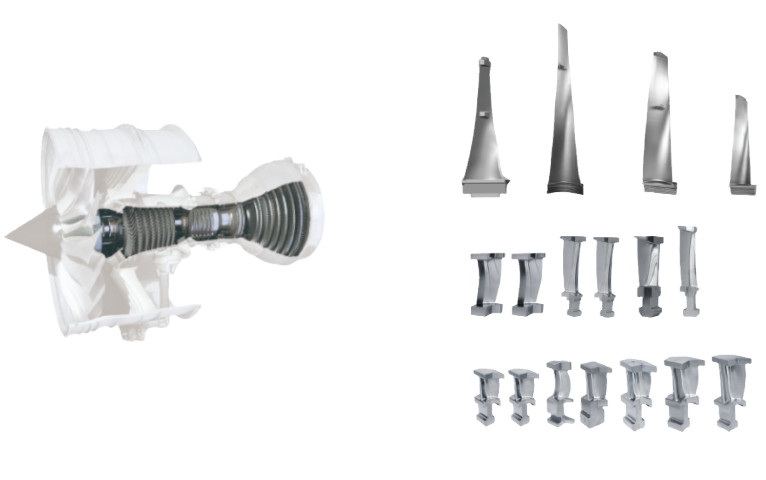
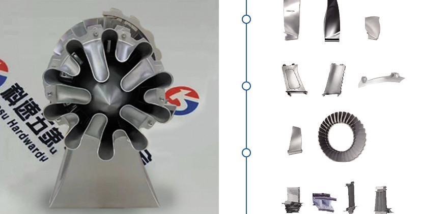
Kesu serves the globally renowned aero engine companies. We provide turbine impellers, guide vanes, compressor blades and the final machined turbine blades. Products are made of titanium alloys, high-temperature alloys and aluminum alloys. Be capable of manufacturing high quality forging, machining, special processes (shot peening, sand blasting, vibrating finishing, coating) and inspection for fan blades, guide vanes and compressor blades. Have the capability of full manufacturing processes for turbine blades after casting (grinding, vacuum heat treatment, drilling, thermal barrier coating, vacuum brazing and inspection).
Quality Control and Inspection
Quality control is critical in turbine blade manufacturing to ensure performance and safety. Inspection methods include:
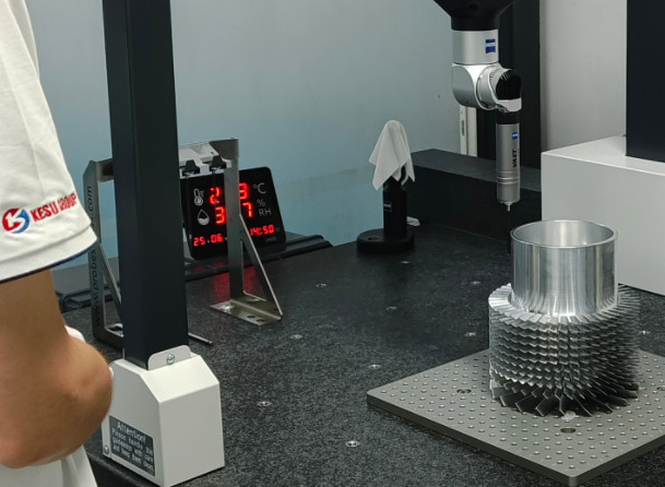
- Coordinate Measuring Machines (CMM): Measure dimensional accuracy with a precision of ±0.002 mm.
- Non-Destructive Testing (NDT): Detects internal defects like cracks or voids using ultrasonic or X-ray methods.
- Optical Metrology: Uses laser scanners to verify complex geometries, achieving resolutions of 0.01 mm.
- Surface Roughness Testing: Ensures surface finish (Ra 0.8–1.6 µm) meets aerodynamic requirements.
These methods verify that blades meet design specifications, ensuring reliability under extreme operating conditions.
Conclusion
Turbine blades, also known as rotor airfoils or vanes, are essential components in aerospace, power generation, and industrial applications. Their manufacturing involves advanced materials like nickel-based superalloys, titanium alloys, and composites, requiring precise machining processes such as investment casting, CNC milling, creep feed grinding, and additive manufacturing. The complexity of blade geometries, tight tolerances, and challenging materials present significant machining difficulties, necessitating specialized tools, optimized toolpaths, and rigorous quality control. By understanding these processes and requirements, manufacturers can produce high-performance turbine blades that meet the stringent demands of modern applications.