Turbine blades are critical core components in aerospace engines, gas turbines, and steam turbines, directly determining the efficiency, reliability, and service life of the entire turbomachinery. Their machining is extremely challenging due to strict requirements on material properties (e.g., high-temperature resistance, corrosion resistance), complex geometric features (e.g., twisted airfoils, thin walls), and ultra-precision surface quality. This guide systematically breaks down the key aspects of turbine blade machining.
Key Characteristics of Turbine Blades: Why Machining Is Challenging
Before delving into machining processes, it is essential to understand the design and material properties that drive machining complexity:
| Characteristic Category | Specific Features | Machining Challenges |
|---|---|---|
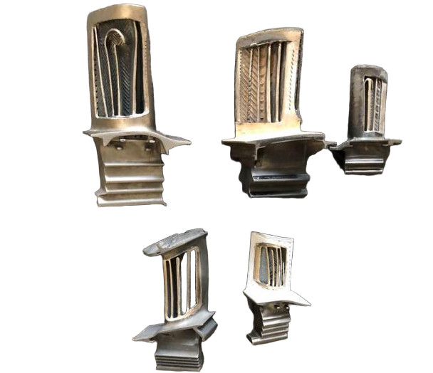
| Geometric Complexity | - Twisted, curved airfoil (to optimize airflow) - Thin-walled structure (3–8 mm thickness in some areas) - Integral root (fir-tree or dovetail shape, for secure installation) - Cooling holes (hundreds to thousands, for high-temperature engines) | - Difficult to maintain dimensional accuracy during cutting - Easy to cause machining deformation (due to uneven stress) - Complex tool paths require high-precision programming |
| Material Properties | - Superalloys (e.g., Inconel 718, Hastelloy): High strength at 600–1000°C, high hardness (HRC 35–45) - Titanium alloys (e.g., Ti-6Al-4V): Low thermal conductivity, high chemical reactivity - Ceramic matrix composites (CMCs): High brittleness, low fracture toughness | - Poor machinability: Rapid tool wear, high cutting force/temperature - Titanium alloys cause "work hardening" (surface hardness increases during cutting) - CMCs are prone to cracking/chipping during machining |
| Precision & Quality Requirements | - Dimensional tolerance: ±0.02–0.05 mm (airfoil profile) - Surface roughness: Ra ≤ 0.8 μm (to reduce airflow resistance) - No microcracks (to avoid fatigue failure under cyclic loads) | - Requires ultra-precision machining equipment - Strict process control to prevent surface defects - 100% inspection (e.g., 3D scanning) is often mandatory |
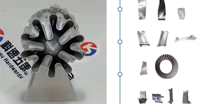
Classification of Turbine Blades (by Application)
Different application scenarios impose distinct requirements on blades, which in turn affect machining strategies:
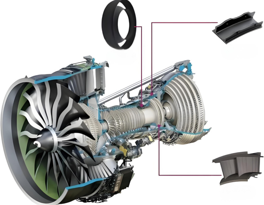
- Aerospace Engine Blades: The most demanding category. Materials are typically superalloys or titanium alloys, with complex internal cooling channels (for jet engines). Machining requires nanoscale precision to withstand extreme temperatures (up to 1,200°C) and aerodynamic loads.
- Gas Turbine Blades (for power generation): Used in natural gas-fired power plants. Materials include superalloys (for high-temperature sections) or stainless steel (for low-temperature sections). Focus on corrosion resistance and long service life (≥20 years).
- Steam Turbine Blades: Applied in thermal power plants. Materials are mostly stainless steel or alloy steel, with larger sizes (some blades exceed 1 meter in length). Machining emphasizes rigidity to handle high-pressure steam.
Core Machining Processes for Turbine Blades
Turbine blade machining is a multi-step, multi-technology integrated process, usually divided into three stages: blank preparation, rough machining, and finish machining.
Blank Preparation: Laying the Foundation
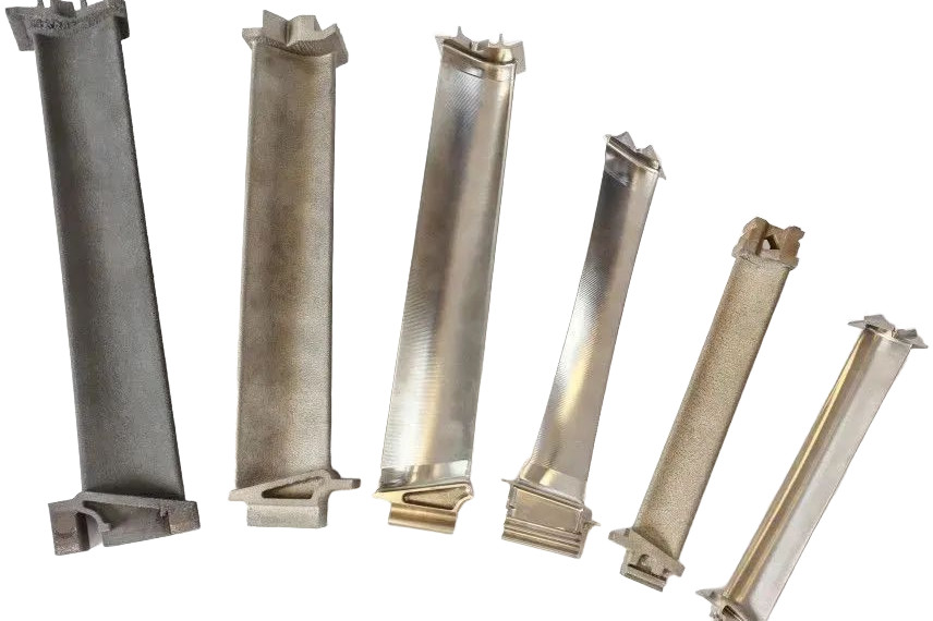
The blank directly affects subsequent machining efficiency and part quality. Common blank forms include:
- Forged Blanks: Dominant for superalloys/titanium alloys. Forging eliminates material internal defects (e.g., pores) and improves grain structure, enhancing blade fatigue resistance. However, forging has low material utilization (only 20–30% for complex blades), increasing costs.
- Cast Blanks: Used for some low-load blades (e.g., steam turbine low-pressure blades). Investment casting (lost-wax casting) can form near-net-shape airfoils, reducing subsequent machining workload.
- Additive Manufacturing (AM) Blanks: A rapidly developing technology (e.g., laser powder bed fusion, LPBF). AM can directly fabricate blades with complex internal cooling channels (which are impossible with forging/casting) and improve material utilization to 80%+ (e.g., GE’s LEAP engine blades). However, AM blanks require post-machining (e.g., surface polishing) to meet precision requirements.
Rough Machining: Removing Excess Material
The goal of rough machining is to quickly remove most of the blank’s excess material, approaching the final shape, while minimizing residual stress (to avoid deformation in finish machining).
| Machining Process | Application Scenario | Key Parameters & Tools |
|---|---|---|
| CNC Milling | Machining blade roots (fir-tree/dovetail) and platforms. | - Machines: 5-axis CNC milling centers (for flexible tool paths) - Tools: Carbide end mills (coated with TiAlN or TiCN to improve wear resistance) - Cutting Parameters: Low cutting speed (vc = 20–50 m/min for Inconel 718) to avoid overheating. |
| Turning | Machining cylindrical features (e.g., blade shanks) or circular platforms. | - Machines: CNC lathes with live tooling - Tools: Ceramic inserts (for high-hardness materials) or CBN (cubic boron nitride) inserts (for finishing rough turning of superalloys). |
| High-Speed Machining (HSM) | Used for titanium alloys (to reduce work hardening). | - Cutting Speed: vc = 80–150 m/min (higher than traditional milling) - Advantage: Reduces cutting force (by 30–50% vs. traditional methods), minimizing blank deformation. |
Finish Machining: Achieving Ultra-Precision & Surface Quality
Finish machining determines the final dimensional accuracy, surface roughness, and mechanical properties of the blade. It requires strict control of cutting parameters and tool selection.
Airfoil Machining (the Most Critical Step)
The airfoil’s twisted, curved shape demands high-precision tool path planning and machine tool rigidity.
- Process: 5-axis CNC flank milling or point milling.
- Flank Milling: Uses the side of the cutting tool to machine the airfoil surface. Advantages: High machining efficiency, good surface continuity. Suitable for blades with large radii of curvature.
- Point Milling: Uses the tip of the tool to machine the airfoil (like "carving" layer by layer). Advantages: High flexibility, suitable for blades with complex, small-radius airfoils (e.g., aerospace engine high-pressure blades).
- Tools:
- Solid carbide ball-end mills (for point milling, coated with AlCrN to resist high temperatures).
- Indexable insert mills (for flank milling, with sharp cutting edges to reduce surface scratches).
- Precision Control: Uses on-machine measurement (OMM) to real-time correct tool wear and machining errors (e.g., Renishaw probes), ensuring airfoil tolerance within ±0.02 mm.
Cooling Hole Machining (for High-Temperature Blades)
Modern aerospace engine blades require hundreds of micro cooling holes (diameter: 0.5–2 mm) to cool the blade surface (reducing temperature by 200–300°C). Traditional drilling is ineffective for superalloys/CMCs, so non-traditional machining is used:
- Electrical Discharge Machining (EDM): Uses electrical sparks to erode material. Suitable for superalloys, but slow (drilling one hole takes 10–30 seconds).
- Laser Drilling: Uses high-power lasers (e.g., fiber lasers) to vaporize material. Advantages: High speed (100+ holes per minute), no tool wear. Disadvantages: May leave recast layers (needs post-treatment like chemical etching to remove).
Surface Finishing
To reduce airflow resistance and improve fatigue life, surface finishing is critical:
- Grinding: Uses CNC creep-feed grinding for airfoil surfaces. Achieves surface roughness Ra = 0.2–0.4 μm and corrects minor dimensional deviations from milling.
- Polishing:
- Mechanical Polishing: Manual or robotic polishing (for complex airfoils) to remove grinding marks.
- Chemical Mechanical Polishing (CMP): For superalloys/CMCs. Combines chemical etching and mechanical grinding to achieve Ra ≤ 0.1 μm (mirror-like surface).
Key Technologies Supporting Turbine Blade Machining
5-Axis CNC Machining Centers
The "backbone" of turbine blade machining. 5-axis machines (3 linear axes + 2 rotational axes) can adjust the tool posture in real time, ensuring the cutting tool maintains the optimal angle with the airfoil surface—solving the problem of machining "shadow areas" in complex shapes. Top brands include DMG MORI (Germany), Mazak (Japan), and GF Machining Solutions (Switzerland).
Computer-Aided Manufacturing (CAM) Software
Critical for tool path planning. Advanced CAM software (e.g., Siemens NX CAM, Autodesk PowerMill) can:
- Generate interference-free tool paths (avoiding tool collisions with the blade root/platform).
- Simulate the entire machining process (to detect errors in advance).
- Optimize cutting parameters (e.g., feed rate, depth of cut) based on material properties (e.g., reducing feed rate for thin-walled sections to prevent deformation).
Advanced Cutting Tools
Tool performance directly affects machining efficiency and part quality. For difficult-to-machine materials:
- Superhard Tools: CBN (for superalloys) and diamond tools (for titanium alloys/CMCs). CBN tools can withstand cutting temperatures up to 1,200°C, reducing tool changes by 50% vs. carbide tools.
- Coated Tools: AlCrN (aluminum chromium nitride) coatings have better high-temperature resistance than traditional TiAlN coatings, extending tool life by 2–3 times when machining Inconel 718.
Quality Inspection: Ensuring Reliability
Turbine blades operate under extreme conditions (high temperature, high pressure, cyclic loads), so 100% quality inspection is mandatory. Common inspection methods include:
- 3D Optical Scanning: Uses laser scanners (e.g., Hexagon, Keyence) to capture the entire blade’s 3D geometry, comparing it with the CAD model to check dimensional accuracy (tolerance, profile deviation).
- Ultrasonic Testing (UT): Detects internal defects (e.g., cracks, inclusions) in the blade, especially critical for forged or AM blanks.
- Surface Roughness Testing: Uses contact or non-contact profilometers to measure surface roughness (Ra/Rz) and ensure compliance with design requirements.
- Metallographic Inspection: Samples are taken from blade blanks/machined parts to check grain structure and material uniformity (e.g., ensuring no coarse grains in superalloy blades).
Conclusion
In summary, turbine blade machining is a highly integrated discipline combining material science, precision machining, software simulation, and quality control. As turbomachinery demands higher efficiency and sustainability, machining technologies will continue to evolve toward higher precision, intelligence, and greenness.