Turbine rotor machining is a critical process in the manufacturing of turbomachinery, such as gas turbines, steam turbines, and compressors, used in power generation, aerospace, and industrial applications. The rotor, a central component, must withstand extreme mechanical and thermal stresses while maintaining precise dynamic balance and structural integrity. This guide provides a systematic overview of the machining processes, detailed parameters, and key considerations to ensure high-quality rotor production. Drawing from established industry practices, it emphasizes technical precision, reliability, and systematic execution.
Overview of Turbine Rotor Machining
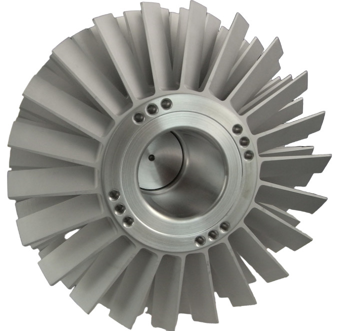
Turbine rotors consist of a shaft, disks or drums, and often blades or blade slots, typically made from high-strength materials like nickel-based superalloys, titanium alloys, or high-grade steels. Machining these components requires advanced equipment, such as CNC lathes, milling machines, and grinding systems, to achieve tight tolerances and surface finishes. The process involves multiple stages, including forging, rough machining, heat treatment, finish machining, and balancing. Each stage demands precise control to meet performance and safety requirements.
The primary goal is to produce a rotor with accurate geometry, minimal residual stresses, and optimal dynamic behavior. For example, coaxiality errors in rotor machining must be kept below 10-30 µm to ensure stability at high rotational speeds, as seen in molecular pumps with magnetic suspension. This level of precision reduces centrifugal forces and enhances operational reliability.
Key Machining Processes
Turbine rotor machining encompasses several specialized processes, each tailored to specific component features and material properties. The following subsections detail the most common techniques, their parameters, and execution requirements.
Turning Operations
Turning is the primary method for machining rotor shafts and cylindrical features of disks or drums. CNC lathes with high rigidity are used to handle the tough materials and large workpiece sizes. Key parameters include:
- Cutting Speed: 20-50 m/min for nickel-based alloys, 80-120 m/min for titanium alloys.
- Feed Rate: 0.1-0.3 mm/rev for roughing, 0.05-0.1 mm/rev for finishing.
- Depth of Cut: 1-3 mm for roughing, 0.2-0.5 mm for finishing.
- Tool Material: Carbide or cubic boron nitride (CBN) for superalloys, coated carbide for titanium.
During turning, coolant is critical to manage heat generation, especially for superalloys, which have low thermal conductivity. For example, a high-pressure coolant system (50-70 bar) is often used to extend tool life and improve surface finish. The surface roughness target is typically Ra 0.8-1.6 µm for functional surfaces.
Milling Operations
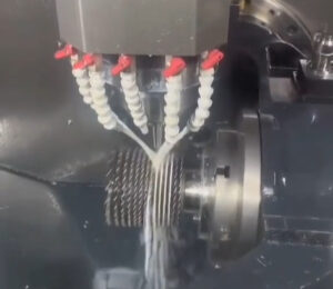
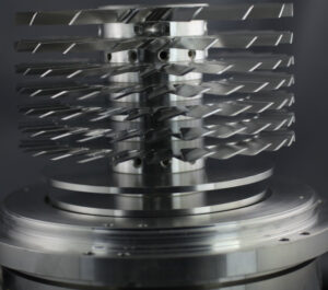
Milling is employed for complex features, such as blade root slots, disk profiles, and cooling channels. Five-axis CNC milling machines are preferred for their ability to handle intricate geometries. Common milling strategies include flank milling and point milling, with the following parameters:
- Spindle Speed: 3,000-10,000 RPM, depending on tool diameter and material.
- Feed Rate: 0.05-0.15 mm/tooth for flank milling, 0.02-0.08 mm/tooth for point milling.
- Depth of Cut: 0.5-1.5 mm for roughing, 0.0-0.5 mm for finishing.
- Tool Type: Solid carbide or CBN-coated tools for superalloys; lollipop cutters for integral shroud milling.
Flank milling is faster but less accurate, suitable for ruled surfaces, while point milling provides superior precision for non-ruled surfaces, such as axial compressor blades. For example, milling turbine blade slots in Inconel 718 requires tolerances of ±0.01 mm to ensure proper blade attachment and stress distribution.
Grinding Operations
Grinding is used for finishing critical surfaces, such as bearing journals and blade root slots, to achieve high dimensional accuracy and surface quality. Electroplated CBN tools are effective for grinding superalloys due to their wear resistance. Typical parameters include:
- Wheel Speed: 20-30 m/s for CBN wheels.
- Workpiece Speed: 5-10 m/min.
- Infeed Rate: 0.005-0.02 mm/pass for finishing.
- Surface Finish: Ra 0.2-0.4 µm for bearing surfaces.
Grinding reduces burr formation compared to milling, lowering deburring costs. For instance, tests at specialized grinding centers have shown that CBN grinding can reduce cycle times by up to one-third compared to broaching for turbine rotor slots.
Balancing and Inspection
Dynamic balancing is essential to minimize vibration and extend rotor lifespan. Rotors are spun at or near operational speeds (e.g., 3,000-10,000 RPM) to detect and correct imbalances. Corrections involve adding or removing material at specific planes, with balance grades adhering to ISO 1940 standards (e.g., G2.5 for turbines). Inspection techniques include:
- Coordinate Measuring Machines (CMM): For dimensional accuracy (tolerances ±0.005 mm).
- Ultrasonic Testing: To detect internal defects in forgings.
- Magnetic Particle Inspection: For surface crack detection.
Balancing and inspection ensure that critical speeds—where vibrations peak—are avoided during operation, preventing catastrophic failures.
Material Considerations
Turbine rotors are typically made from materials like Inconel 718, Ti-6Al-4V, or 1.6979 steel, selected for their high strength, creep resistance, and fatigue properties. These materials pose machining challenges due to their hardness (30-45 HRC) and low machinability. Key material-specific considerations include:
| Material | Hardness (HRC) | Machining Challenges | Recommended Tools |
|---|---|---|---|
| Inconel 718 | 36-44 | High cutting forces, rapid tool wear | CBN, ceramic inserts |
| Ti-6Al-4V | 32-36 | Heat buildup, chemical reactivity | Coated carbide |
| 1.6979 Steel | 28-34 | Moderate wear, good machinability | Carbide inserts |
Heat treatment, such as stress relieving at 27-55°C below tempering temperature for 1 hour per inch of thickness, is applied post-rough machining to stabilize material properties. Microstructure requirements, such as tempered martensite or bainite with no free ferrite, are verified per ASTM E45 and E112 standards.
Critical Parameters and Tolerances
Achieving precise tolerances is paramount in turbine rotor machining to ensure performance and safety. The following table summarizes key parameters and tolerances for common rotor features:
| Feature | Tolerance | Surface Finish (Ra, µm) | Inspection Method |
|---|---|---|---|
| Shaft Diameter | ±0.01 mm | 0.8-1.6 | CMM, micrometer |
| Blade Root Slot | ±0.005 mm | 0.4-0.8 | CMM, profile projector |
| Bearing Journal | ±0.002 mm | 0.2-0.4 | CMM, surface tester |
Coaxiality errors must be minimized to prevent vibration. For example, a clamping accuracy detection system can reduce coaxiality errors from 30 µm to 10 µm, enhancing rotor stability. Critical speed analysis, using finite element methods (e.g., Dynrot software), identifies resonance frequencies to ensure safe operation.
Quality Assurance and Testing
Quality assurance involves rigorous testing to validate rotor integrity and performance. Key tests include:
- Heat Stability Test: Per SEP 1950, conducted post-heat treatment to verify dimensional stability.
- Spin Testing: At speeds up to 10,000 RPM to assess dynamic behavior and detect flaws.
- Non-Destructive Testing (NDT): Ultrasonic and magnetic particle inspections to ensure defect-free forgings.
Data from spin tests, such as blade tip clearance and shaft displacement, are analyzed using sensors (e.g., microwave or capacitive) to develop health monitoring systems. These tests confirm that rotors meet design specifications and can operate safely under extreme conditions.
Practical Considerations
Several practical considerations enhance the efficiency and reliability of turbine rotor machining:
- Tool Path Optimization: CAM software, such as MAX-PAC, generates efficient tool paths for five-axis milling, reducing machining time and improving surface quality.
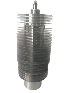
- Fixturing: Robust fixtures minimize workpiece deflection, especially for large rotors (e.g., >500 tons for LP steam turbines).
- On-Site Machining: Mobile lathes enable in-place repairs, reducing downtime and transportation costs.
For example, in-place machining of a damaged steam turbine rotor shaft (e.g., reducing diameter by 0.6165 inches to remove a 0.58-inch groove) can save significant costs compared to full disassembly.
Conclusion
Turbine rotor machining is a complex, multi-stage process requiring advanced equipment, precise parameters, and rigorous quality control. By adhering to established techniques—turning, milling, grinding, and balancing—manufacturers can produce rotors that meet stringent performance and safety requirements. Detailed attention to material properties, tolerances, and testing ensures reliability in demanding applications. This guide provides a comprehensive framework for professionals seeking to optimize rotor machining processes, grounded in technical expertise and systematic execution.