Ultra precision machining represents a specialized domain within manufacturing engineering focused on achieving exceptional levels of accuracy and surface quality in component production. This process enables the fabrication of parts with tolerances in the sub-micrometer range and surface roughness values below 10 nanometers. It is essential for industries requiring high-performance components, such as optics, aerospace, and microelectronics. The following sections detail the core elements, techniques, equipment, materials, parameters, measurement methods, and industrial applications of ultra precision machining, emphasizing technical specifications and systematic approaches.
Definition and Key Characteristics
Ultra precision machining is defined as a subtractive manufacturing process that produces components with form accuracy better than 1 micrometer and surface roughness less than 50 nanometers. Unlike conventional machining, which typically operates at tolerances of 10 micrometers or more, ultra precision methods achieve nanometric precision through rigid machine structures, high-resolution motion control, and environmental isolation. Key characteristics include dimensional stability at the atomic scale, minimal subsurface damage, and repeatability across production runs.
The process relies on single-point or multi-point cutting tools, often diamond-based, to remove material in controlled layers. For instance, in diamond turning, the tool nose radius can be as small as 0.1 millimeters, enabling mirror-like finishes without secondary polishing. Surface integrity is maintained by limiting cutting forces to below 1 Newton, reducing thermal distortion and vibration effects. This machining category encompasses operations where the ratio of uncut chip thickness to tool edge radius approaches unity, demanding precise kinematic control.
Fundamental metrics include form error, quantified as peak-to-valley deviation (PV) less than 0.5 micrometers over 100 millimeters, and waviness controlled to under 20 nanometers per millimeter. These parameters ensure components meet stringent optical or mechanical performance criteria, such as in aspheric lenses where surface form directly influences light refraction efficiency.
Machining Techniques
Several techniques dominate ultra precision machining, each tailored to specific geometries and materials. Single-point diamond turning (SPDT) is a primary method, utilizing a monocrystalline diamond tool on a lathe-like setup to generate rotationally symmetric surfaces. In SPDT, the spindle speed ranges from 500 to 3000 revolutions per minute, with feed rates as low as 0.1 micrometers per revolution to achieve surface roughness Ra of 1-5 nanometers.
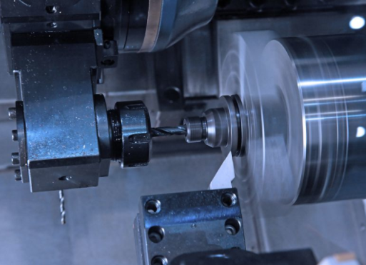
Ultra precision milling extends this to non-symmetric features, employing end mills with diameters down to 0.05 millimeters. Cutting speeds are maintained at 10-50 meters per minute, with depth of cut limited to 1-10 micrometers per pass. This technique is suitable for micro-structured surfaces, where tool path interpolation accuracy must be within 50 nanometers.
Diamond grinding and fly-cutting are additional variants. In grinding, abrasive wheels with grain sizes of 1-5 micrometers operate at peripheral speeds of 20-40 meters per second, producing flatness deviations below 0.2 micrometers over 200 millimeters. Fly-cutting involves a single-point tool traversing a rotating workpiece, ideal for large planar optics with surface finishes under 2 nanometers RMS.
Electrochemical machining hybrids, such as electrolytic in-process dressing (ELID) grinding, enhance precision by continuously sharpening the wheel, achieving subsurface damage depths less than 100 nanometers. These techniques integrate feedback loops for real-time adjustment, ensuring consistent removal rates of 0.01-0.1 micrometers per minute.
Machine Tools and Equipment
Ultra precision machine tools feature hydrostatic or aerostatic bearings for frictionless motion, with stiffness exceeding 100 Newtons per micrometer. Linear axes employ laser interferometry for positioning resolution of 1 nanometer, while rotary axes use air-bearing spindles with radial runout below 25 nanometers.
Common configurations include two-axis diamond turning lathes with X-Z travels up to 500 millimeters, and five-axis machining centers for complex geometries. Vibration isolation is achieved through granite bases mounted on active dampers, attenuating external disturbances to less than 1 nanometer amplitude at frequencies above 1 Hertz.
Tool holders incorporate piezoelectric actuators for fine adjustment, with response times under 1 millisecond. Environmental enclosures maintain temperature stability to ±0.01 degrees Celsius and humidity at 50% ±1%, preventing thermal expansion coefficients from affecting accuracy—typically 10-20 parts per million per degree for machine materials like Invar.
Control systems utilize CNC with sub-nanometer interpolation, often based on EtherCAT protocols for synchronization latencies below 100 microseconds. Metrology integration, such as on-machine probing with capacitance sensors, allows closed-loop corrections with repeatability of 5 nanometers.
Materials Processed
Ultra precision machining is applicable to ductile materials that exhibit low brittleness under fine cutting conditions. Non-ferrous metals like aluminum 6061 and copper alloys are common, with shear strengths around 200-400 MPa, allowing chip formation without fracture at depths below 1 micrometer.
Optical glasses, such as BK7 with hardness of 500 Vickers, require diamond tools to achieve optical clarity, with removal rates of 0.005 cubic millimeters per second. Semiconductors like silicon (111) orientation are machined for infrared optics, maintaining crystallographic integrity to avoid anisotropic effects.
Polymers including polycarbonate and PMMA are processed for lightweight optics, with low modulus of elasticity (2-3 GPa) necessitating reduced cutting forces below 0.5 Newtons to prevent elastic recovery. Ceramics like Zerodur, with thermal expansion near zero, are ground to flatness of 0.1 micrometers for telescope mirrors.
Material selection considers machinability indices, where diamond-compatible substances exhibit high thermal conductivity (above 100 W/m·K) to dissipate heat, minimizing subsurface damage to depths less than 50 nanometers.
Process Parameters and Control
Critical parameters in ultra precision machining include cutting speed, feed rate, depth of cut, and tool geometry. For diamond turning of aluminum, optimal cutting speeds are 100-200 meters per minute, with feed rates of 2-5 micrometers per revolution and depths of 1-10 micrometers, yielding surface roughness Ra of 3-7 nanometers.
Tool rake angles range from -5 to +5 degrees to optimize shear plane angles, while clearance angles of 5-10 degrees reduce friction coefficients to below 0.1. Coolant application, often mist or cryogenic, controls chip temperature to under 50 degrees Celsius, preserving tool life beyond 10 kilometers of cutting distance.
Control strategies involve adaptive feedforward compensation for geometric errors, using polynomials up to 10th order for axis calibration. Vibration monitoring with accelerometers sensitive to 1 micro-g ensures dynamic stability, with natural frequencies above 100 Hertz for machine structures.
Parameter optimization employs finite element analysis to predict residual stresses below 50 MPa, integrating thermal models with conductivity values of 200 W/m·K for tool materials. Real-time monitoring via force sensors with 0.01 Newton resolution adjusts parameters to maintain constant chip thickness ratios.
Key Process Parameters Table
| Technique | Cutting Speed (m/min) | Feed Rate (μm/rev) | Depth of Cut (μm) | Surface Roughness (nm Ra) |
|---|---|---|---|---|
| Single-Point Diamond Turning | 50-300 | 0.5-5 | 1-20 | 1-10 |
| Ultra Precision Milling | 10-100 | 0.1-2 | 0.5-5 | 2-15 |
| Diamond Grinding | 20-50 | 1-10 | 0.1-1 | 0.5-5 |
Measurement and Quality Assurance
Quality assurance in ultra precision machining employs non-contact metrology tools for sub-nanometer resolution. Interferometry, such as Twyman-Green setups, measures form errors with wavelengths of 632.8 nanometers, achieving uncertainties of 10 nanometers over 300 millimeters.
Surface profilometry using atomic force microscopy (AFM) scans areas up to 100 micrometers square, quantifying roughness with vertical resolution of 0.1 angstroms. Coordinate measuring machines (CMMs) with laser trackers provide volumetric accuracy of 0.5 micrometers + 0.5 ppm.
In-process monitoring integrates capacitive gauges for tool-workpiece distance control to 5 nanometers, while post-process inspection uses white light interferometry for areal topography with lateral resolution of 0.5 micrometers.
Statistical process control applies Six Sigma methodologies, targeting CpK values above 2.0 for critical dimensions. Calibration standards trace back to NIST artifacts, ensuring traceability with expanded uncertainties below 20 nanometers.
Applications in Industry
In optics manufacturing, ultra precision machining produces aspheric lenses for telescopes, with diameters up to 1 meter and sagitta deviations under 0.2 micrometers. These components enable diffraction-limited performance in systems like Hubble Space Telescope mirrors.
Aerospace applications include turbine blades with airfoil tolerances of 5 micrometers, reducing drag coefficients by 2-5%. Microelectronics benefit from machined molds for semiconductor packaging, achieving feature sizes below 10 micrometers.
Medical devices, such as intraocular lenses, require surface finishes below 5 nanometers Ra to minimize scattering, while automotive sector uses the process for fuel injector nozzles with hole diameters of 50 micrometers ±0.5 micrometers.
Defense systems incorporate ultra precision components in gyroscopes, where rotational symmetry errors are limited to 0.1 micrometers for inertial navigation accuracy of 0.01 degrees per hour.
Industrial Applications Table
| Industry | Component Examples | Key Specifications |
|---|---|---|
| Optics | Aspheric Lenses, Mirrors | Form Accuracy < 0.5 μm, Roughness < 5 nm |
| Aerospace | Turbine Blades, Sensors | Tolerances < 10 μm, Flatness < 1 μm |
| Microelectronics | Molds, Wafer Chucks | Feature Size < 20 μm, Alignment < 0.1 μm |
| Medical | Implants, Lenses | Surface Ra < 10 nm, Dimensional ±1 μm |