
Ensuring the accuracy of vacuum pump blade profiles is critical in industries such as aerospace, semiconductor manufacturing, and chemical processing, where precision directly impacts performance and efficiency. Coordinate Measuring Machines (CMMs) are advanced metrology tools that provide micron-level accuracy for verifying complex geometries like vacuum pump blades. This guide outlines a systematic approach to using CMMs for verifying blade profile accuracy, emphasizing technical procedures, key parameters, and practical considerations to achieve reliable results.
Understanding Vacuum Pump Blade Profile Requirements
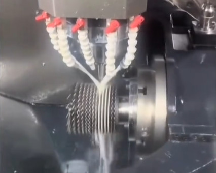
Vacuum pump blades, particularly those in screw vacuum pumps or centrifugal pumps, have intricate geometries that require high precision to ensure optimal performance. The blade profile, including angles, radii, and surface contours, must align with design specifications to maintain pumping efficiency, minimize wear, and prevent operational failures. Deviations in the blade profile can lead to reduced vacuum performance, increased energy consumption, or mechanical imbalances.
The profile accuracy of vacuum pump blades is typically defined by tolerances in the range of ±0.01 mm to ±0.05 mm, depending on the application. For instance, screw vacuum pump rotors often require five-axis CNC machining to achieve the necessary precision, and their helical surfaces demand accurate measurement to confirm compliance with design standards. CMMs are ideal for this task due to their ability to capture three-dimensional coordinates and analyze complex geometries.
Overview of Coordinate Measuring Machines (CMMs)
A CMM is a precision measurement device that uses a probe to collect spatial coordinates (X, Y, Z) from a workpiece's surface. These coordinates are processed by advanced software to create a digital model, which is compared against a CAD design to verify dimensional and geometric accuracy. CMMs are widely used in industries requiring high-precision measurements, such as aerospace and automotive, due to their repeatability, versatility, and ability to measure complex shapes.
Key components of a CMM include:
- Probe System: Contact probes (e.g., touch-trigger or scanning probes) or non-contact probes (e.g., laser or optical) capture surface data.
- Machine Structure: Bridge, gantry, or articulated arm designs provide stability and multi-axis movement.
- Control System: Software interprets probe data, performs calculations, and generates reports.
- Environmental Controls: Temperature and humidity regulation ensure measurement stability.
For vacuum pump blades, bridge-type CMMs are commonly used due to their high accuracy and ability to handle complex geometries. Articulated arm CMMs may be used for larger or more accessible components, but their accuracy is slightly lower, typically ±0.02 mm compared to ±0.002 mm for bridge CMMs.
Steps for Verifying Vacuum Pump Blade Profile Accuracy
Verifying the profile accuracy of vacuum pump blades using a CMM involves a systematic process to ensure repeatability and precision. The following steps outline the procedure:
Step 1: Preparation and Setup
Proper preparation is essential to achieve accurate measurements. The following tasks should be completed:
- Environmental Control: Maintain a stable environment with a temperature of 20±2°C and humidity of 40–60% to minimize thermal expansion or contraction of the blade and CMM components.
- Workpiece Fixturing: Secure the blade using a custom fixture to prevent movement during measurement. The fixture should align the blade’s reference datum with the CMM’s coordinate system.
- Probe Selection: Choose a probe suitable for the blade’s geometry. For complex helical surfaces, a scanning probe with a 2 mm stylus tip is recommended to capture continuous surface data. For smaller features, a 1 mm stylus may be used.
- CMM Calibration: Calibrate the CMM using certified artifacts, such as gauge blocks or calibrated spheres, to verify linear and probing uncertainties. Calibration should comply with standards like ISO 10360-2, ensuring measurement accuracy within ±0.002 mm.
Step 2: Defining the Measurement Strategy
The measurement strategy involves programming the CMM to capture the blade’s critical features. Key considerations include:
- Datum Alignment: Align the blade’s coordinate system with the CAD model using reference points, such as the blade’s mounting surface or centerline. This ensures accurate comparison with design specifications.
- Measurement Points: Define a sufficient number of measurement points to capture the blade’s profile. For helical surfaces, a grid of 100–200 points per section is typical, with a point density of 0.1–0.5 mm.
- Scanning Paths: Use continuous scanning for smooth surfaces like blade profiles to capture detailed contour data. For sharp edges or small radii, discrete point measurements may be necessary to avoid probe contact issues.
The measurement strategy should prioritize critical areas, such as the blade’s leading and trailing edges, where profile deviations have the greatest impact on performance.
Step 3: Data Collection
Execute the measurement program to collect coordinate data. The CMM’s probe moves along predefined paths, recording X, Y, Z coordinates at each point. For a vacuum pump blade, the following parameters are typically measured:
| Parameter | Description | Typical Tolerance |
|---|---|---|
| Profile Deviation | Deviation of the blade’s surface from the nominal CAD profile | ±0.01–0.05 mm |
| Leading Edge Radius | Radius of the blade’s leading edge | ±0.02 mm |
| Helical Angle | Angle of the blade’s helical surface relative to the axis | ±0.1° |
| Surface Roughness | Surface finish affecting flow efficiency | Ra 0.8–1.6 µm |
Scanning probes should operate at a speed of 1–5 mm/s to balance accuracy and efficiency. Faster speeds may reduce accuracy, while slower speeds increase measurement time.
Step 4: Data Analysis and Comparison
CMM software processes the collected coordinates to generate a point cloud, which is compared to the nominal CAD model. Key analyses include:
- Profile Tolerance: Calculate the maximum deviation between the measured and nominal profiles. ISO 1101 defines profile tolerance as the allowable deviation within a specified zone.
- Geometric Analysis: Verify angles, radii, and positional accuracy of features like the blade’s leading edge or helical surface.
- Surface Profiling: Generate a 3D surface map to identify deviations in curvature or surface finish.
The software may produce a color-coded deviation map, where green indicates compliance (within ±0.01 mm), yellow indicates marginal deviation (±0.01–0.03 mm), and red indicates out-of-tolerance areas (>0.03 mm).
Step 5: Reporting and Validation
Generate a comprehensive report summarizing the measurement results. The report should include:
- Measurement parameters (e.g., number of points, probe type).
- Deviation data, including maximum and minimum deviations.
- Graphical representations, such as deviation maps or cross-sectional profiles.
- Compliance status with respect to design tolerances.
Validate the results by repeating measurements on a subset of points to confirm repeatability, typically within ±0.002 mm. If deviations exceed tolerances, investigate potential causes, such as machining errors or fixture misalignment.

Key Parameters for Accurate CMM Measurements
To ensure reliable results, specific parameters must be controlled during the measurement process. The following table summarizes critical parameters and their recommended values:
| Parameter | Recommended Value | Purpose |
|---|---|---|
| Probe Diameter | 1–2 mm | Balances resolution and access to small features |
| Measurement Point Density | 0.1–0.5 mm | Ensures sufficient data for complex geometries |
| Scanning Speed | 1–5 mm/s | Maintains accuracy without excessive time |
| Environmental Temperature | 20±2°C | Minimizes thermal distortion |
| Calibration Frequency | Daily or per shift | Ensures probe and machine accuracy |
Practical Considerations for CMM Measurement
Several factors can affect the accuracy of CMM measurements for vacuum pump blades. Addressing these ensures reliable results:
- Probe Wear: Inspect and replace worn probes to prevent measurement errors. A worn stylus tip can introduce errors of up to 0.005 mm.
- Fixture Stability: Use rigid, custom-designed fixtures to eliminate movement. Misalignment can cause errors of 0.01–0.02 mm.
- Surface Cleanliness: Remove contaminants like oil or dust from the blade surface to avoid probe interference.
- Software Capabilities: Ensure the CMM software supports advanced geometric analysis, such as helical surface evaluation, to handle the blade’s complex shape.
Regular maintenance of the CMM, including cleaning air bearings and updating software, is essential to maintain accuracy over time. Calibration checks should be performed daily or per shift, using certified artifacts to verify measurement uncertainty.
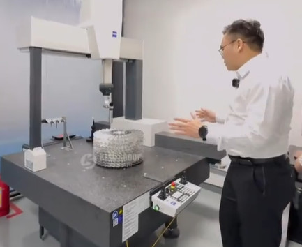
Case Study: Measuring a Screw Vacuum Pump Rotor
Consider a screw vacuum pump rotor with a helical blade profile, designed with a tolerance of ±0.02 mm for profile deviation and ±0.1° for helical angle. A bridge-type CMM with a 2 mm scanning probe was used to measure the rotor. The measurement strategy involved:
- Aligning the rotor’s centerline with the CMM’s coordinate system using three reference points.
- Collecting 150 points per cross-section at 0.2 mm intervals along the helical surface.
- Scanning at 3 mm/s to balance speed and accuracy.
- Comparing the point cloud to the CAD model using CMM software.
The results showed a maximum profile deviation of 0.015 mm and a helical angle deviation of 0.08°, both within tolerance. A deviation map highlighted a slight curvature error near the leading edge, which was corrected by adjusting the CNC machining parameters.
Conclusion
Verifying the profile accuracy of vacuum pump blades using a CMM is a systematic process that requires careful preparation, precise measurement strategies, and thorough data analysis. By controlling environmental conditions, selecting appropriate probes, and adhering to calibration standards, manufacturers can achieve micron-level accuracy and ensure compliance with design specifications. The outlined steps and parameters provide a reliable framework for quality control, enabling consistent performance in demanding applications.