Wheel hub machining involves shaping the central component of a vehicle's wheel assembly, connecting the wheel to the suspension and axle. Known as the wheel hub unit, bearing assembly, or wheel carrier, this component requires precision to meet automotive standards for performance, durability, and safety. Machining operations include turning, drilling, milling, boring, and finishing, applied to materials like aluminum alloys, cast iron, or steel. The goal is to achieve tight tolerances, smooth surfaces, and reliable functionality under dynamic loads.
Key Components of a Wheel Hub
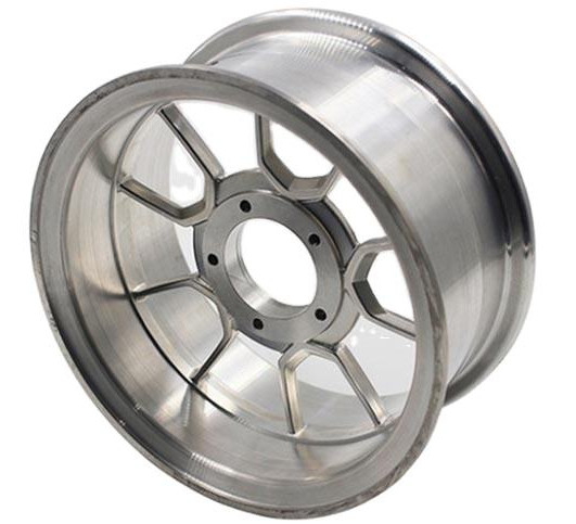
The wheel hub assembly integrates critical elements for vehicle operation. The hub, a forged or cast metal part, houses the wheel bearing for smooth rotation. It typically includes a flange for mounting the brake rotor or drum and bolt holes for securing the wheel. Features like splines for driven hubs or tone rings for ABS sensors may be included. Understanding these components guides machining to ensure compatibility and performance.
| Component | Function | Material | Machining Requirement |
|---|---|---|---|
| Hub Body | Connects wheel to axle | Aluminum alloy, cast iron | Turning, milling for precise diameter |
| Flange | Mounts brake rotor/wheel | Same as hub body | Drilling, surface finishing |
| Bearing Housing | Holds wheel bearing | Steel, aluminum | Boring, tight tolerance machining |
| Splines (Driven Hubs) | Transfers torque | Steel | Milling, precision shaping |
Materials Used in Wheel Hub Manufacturing
Material selection balances strength, weight, and machinability. Common materials include aluminum alloys (e.g., A356, 6061-T6) for lightweight applications, cast iron for durability in heavy-duty vehicles, and steel for high-strength driven hubs. Aluminum offers corrosion resistance and reduced weight, cast iron provides cost-effectiveness and wear resistance, and steel withstands high torque. Material properties dictate machining parameters, such as cutting speeds and tool selection.
Machining Processes for Wheel Hubs
Wheel hub machining involves multiple processes tailored to specific features of the hub unit. Below are the primary operations:
Turning
Turning shapes the outer and inner diameters of the hub body and bearing housing. CNC lathes achieve tolerances as tight as ±0.01 mm. For aluminum hubs, cutting speeds range from 200 to 400 m/min with carbide tools, while cast iron requires 100 to 200 m/min to prevent tool wear. Vertical lathes with inverted spindles are often used for high-volume production, minimizing chip buildup.
Drilling
Drilling creates bolt holes in the flange for wheel and brake rotor mounting. High-speed steel (HSS) or carbide drills operate at 1,000–1,500 rpm with feed rates of 0.05 to 0.2 mm/rev. A standard five-lug hub has hole diameters of 12–14 mm, with positional tolerances of ±0.05 mm to ensure alignment. Coolant prevents overheating and ensures hole accuracy.
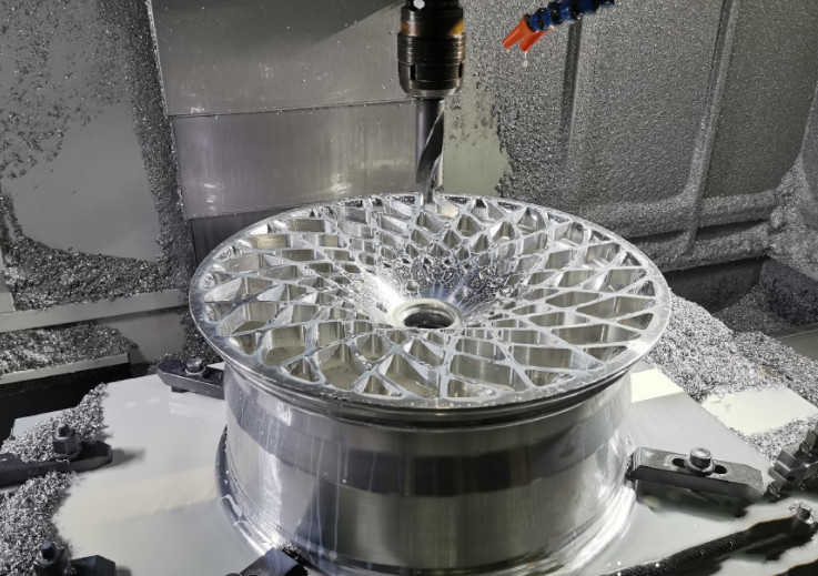
Milling
Milling forms features like splines, keyways, or tone ring surfaces. For driven hubs, spline milling requires precision to maintain torque transfer efficiency. CNC machining centers with high-speed spindles (up to 20,000 rpm) achieve surface roughness of Ra 0.8 to 1.6 µm for critical contact areas. Cutting speeds for aluminum reach 300–500 m/min, while steel requires 100–200 m/min.
Boring
Boring refines the bearing housing for precise bearing fit, with tolerances of ±0.005 mm to prevent misalignment. Carbide-tipped tools with coolant reduce heat and extend tool life. This operation is critical for hub assemblies with integrated bearings, ensuring smooth rotation and longevity.
Finishing
Finishing processes like grinding or polishing achieve surface roughness as low as Ra 0.4 µm for bearing contact surfaces, reducing friction and enhancing durability. Flanges may undergo deburring or shot blasting to remove sharp edges, improving safety and appearance.
Tooling and Equipment
CNC machines dominate wheel hub machining for precision and repeatability. Common equipment includes:
- CNC Lathes: For turning and boring, often with live tooling for multi-process capabilities.
- CNC Machining Centers: For milling and drilling, supporting multi-axis operations.
- Grinding Machines: For finishing bearing surfaces and achieving tight tolerances.
- Inspection Equipment: Coordinate measuring machines (CMMs) and laser scanners ensure dimensional accuracy.
Tool materials include carbide, HSS, and ceramic for high-speed applications. Water-based coolant manages heat and chip evacuation, especially for aluminum hubs.
Key Machining Parameters
Machining parameters ensure quality and efficiency. Below are typical parameters for common materials:
| Material | Process | Cutting Speed (m/min) | Feed Rate (mm/rev) | Depth of Cut (mm) |
|---|---|---|---|---|
| Aluminum Alloy | Turning | 200–400 | 0.1–0.3 | 0.5–2.0 |
| Cast Iron | Turning | 100–200 | 0.08–0.2 | 0.5–1.5 |
| Steel | Milling (Splines) | 80–150 | 0.05–0.15 | 0.2–1.0 |
| Aluminum Alloy | Drilling | 150–300 | 0.05–0.2 | Full depth |
Quality Control and Inspection
Quality control ensures wheel hubs meet standards like ISO/TS 16949. Key inspection points include:
- Dimensional Accuracy: CMMs verify tolerances for bearing housing and flange holes.
- Surface Finish: Profilometers measure roughness to ensure Ra 0.4–1.6 µm on critical surfaces.
- Material Integrity: Ultrasonic or magnetic particle testing detects internal defects.
- Assembly Fit: Gauges confirm bearing and wheel mounting compatibility.
In-process inspections reduce defects, while final checks ensure compliance with OEM specifications.
Common Challenges in Wheel Hub Machining
Several difficulties can arise during wheel hub machining, impacting quality and efficiency:
- Tool Wear: Hard materials like steel accelerate wear, requiring frequent tool changes. Using coated carbide or ceramic tools mitigates this issue.
- Thermal Deformation: High cutting speeds generate heat, potentially warping aluminum hubs. Coolant and optimized parameters reduce this risk.
- Tight Tolerances: Achieving ±0.005 mm tolerances for bearing housings demands precise machine calibration and operator skill.
- Chip Management: Aluminum produces long, stringy chips that can clog machines. High-pressure coolant and chip breakers address this problem.
Best Practices for Efficient Machining
To optimize wheel hub machining, manufacturers adopt the following practices:
- Process Integration: Combining operations (e.g., turning and milling) on multi-axis CNC machines reduces setup time.
- Toolpath Optimization: CAM software minimizes non-cutting time and ensures efficient toolpaths.
- Material-Specific Parameters: Adjusting speeds and feeds for aluminum, steel, or cast iron improves tool life and surface quality.
- Automation: Robotic loading and in-process gauging enhance throughput in high-volume production.
Environmental and Safety Considerations
Machining generates waste, including metal chips and coolant. Recycling chips and using eco-friendly coolants reduce environmental impact. Safety measures include proper machine guarding, operator training, and personal protective equipment (PPE) to prevent injuries from rotating tools or flying chips.