Wind turbines are complex systems engineered to convert wind's kinetic energy into electrical power. This article provides a detailed examination of wind turbine structure, focusing on key components, design parameters, and engineering principles. It emphasizes technical specifications and systematic analysis to offer a comprehensive understanding of wind turbine architecture for professionals and engineers.
Overview of Wind Turbine Structure
A wind turbine's structure is designed to capture wind energy efficiently while withstanding environmental loads. The primary components include the foundation, tower, rotor (blades and hub), nacelle, and generator. Each part is engineered to optimize energy production, structural integrity, and longevity, typically exceeding 25 years. The structure must balance aerodynamic efficiency, mechanical stability, and cost-effectiveness.
Main Components of a Wind Turbine
The wind turbine's functionality depends on the seamless integration of its components. Below is a detailed breakdown of each major part and its role in the system.
Foundation
The foundation anchors the turbine to the ground, ensuring stability against wind and gravitational forces. For onshore turbines, concrete gravity foundations are common, typically requiring 800 cubic meters of concrete and weighing around 2,000 tons. Offshore turbines may use monopile, jacket, or floating foundations, depending on water depth and seabed conditions. The foundation must resist overturning moments and vibrational loads.
| Foundation Type | Application | Typical Parameters |
|---|---|---|
| Gravity Foundation | Onshore | 800 m³ concrete, 20-30 m diameter |
| Monopile | Offshore (shallow water) | 5-8 m diameter, 30-60 m length |
| Jacket | Offshore (deep water) | 4-6 legs, 50-100 m height |
Tower
The tower elevates the rotor to access stronger winds at higher altitudes, typically 80-120 meters for onshore turbines and up to 150 meters for offshore models. Towers are usually made of tubular steel with wall thicknesses of 20-40 mm, designed to withstand bending, torsional, and vibrational stresses. Material properties like strength (yield strength ~355 MPa) and stiffness are critical for durability.
Rotor Blades
Rotor blades capture wind energy through aerodynamic lift. Modern blades, often made of fiberglass-reinforced composites, can exceed 170 feet (52 meters) in length for onshore turbines and 351 feet (107 meters) for offshore models like GE’s Haliade-X. Blade design parameters include airfoil shape, chord length, and twist angle, optimized for lift-to-drag ratios. A typical 3-blade rotor has a swept area of 12,000-15,000 m² for a 5 MW turbine.
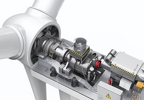
Nacelle
The nacelle houses critical components, including the gearbox, generator, and yaw system. For a 1.5 MW geared turbine, the nacelle weighs approximately 4.5 tons. It is mounted atop the tower and rotates to align with wind direction, ensuring optimal energy capture. The nacelle frame is typically steel, designed to withstand dynamic loads from rotor thrust and wind gusts.
Generator and Drivetrain
The generator converts mechanical energy into electricity. Common types include synchronous, asynchronous (induction), and direct-drive generators. The drivetrain, often including a gearbox, increases rotor speed from 5-25 rpm to 1,000-2,000 rpm for efficient power generation. Direct-drive systems eliminate the gearbox, reducing maintenance but increasing nacelle weight.
Design Parameters of Wind Turbine Structure
Wind turbine design involves optimizing parameters to maximize energy output while ensuring structural integrity. Key parameters include blade length, tower height, material properties, and aerodynamic profiles.
Blade Length and Swept Area
Blade length directly influences the swept area, which determines the amount of wind energy captured. The power output (P) is governed by the equation: P = 0.5 × ρ × A × v³ × Cp, where ρ is air density (1.225 kg/m³), A is swept area, v is wind speed, and Cp is the power coefficient (typically 0.4-0.5 for HAWTs). For a 100-meter blade, the swept area is approximately 31,400 m², enabling multi-megawatt outputs.
Tower Height and Wind Speed
Tower height is critical as wind speed increases with altitude due to reduced surface friction. The wind speed profile follows a logarithmic law: v(z) = v_ref × ln(z/z_0)/ln(z_ref/z_0), where z is height, z_0 is roughness length, and v_ref is reference wind speed. A 100-meter tower can access wind speeds 20-30% higher than at 10 meters, significantly boosting energy yield.
Material Properties
Material selection affects structural performance and cost. Towers use high-strength steel (S355 grade, yield strength 355 MPa), while blades employ composites with tensile strengths of 1,500-2,000 MPa. Fatigue resistance is crucial due to cyclic loading from wind variations. For example, blades endure 10^8 load cycles over their lifespan.
Aerodynamic Design
Blade aerodynamics are optimized using airfoil profiles with high lift-to-drag ratios (typically 80-120). The angle of attack is maintained at 5-10 degrees to maximize lift while avoiding stall. Blade twist and taper ensure uniform loading across the span, reducing fatigue and improving efficiency.
Structural Analysis and Load Considerations
Wind turbines are subjected to complex loads, including aerodynamic, gravitational, centrifugal, and gyroscopic forces. Structural analysis ensures the system can withstand these loads over its operational life.
Aerodynamic Loads
Aerodynamic loads result from wind pressure on blades and tower. For a 5 MW turbine, the thrust force on the rotor can exceed 500 kN at rated wind speeds (11-14 m/s). These loads are calculated using blade-element momentum (BEM) theory, which divides the blade into segments to analyze lift and drag forces.
Gravitational and Centrifugal Loads
Gravitational loads act on blades and the tower, with each blade weighing 15-20 tons for a 5 MW turbine. Centrifugal forces arise from rotor rotation, scaling with the square of rotational speed. For a rotor spinning at 15 rpm, centrifugal forces can reach 100 kN per blade.
Dynamic Loads and Vibration
Dynamic loads from wind gusts and turbulence cause vibrations, analyzed using the Euler-Lagrangian approach. The tower’s natural frequency (typically 0.3-0.5 Hz) must avoid resonance with rotor frequency (0.1-0.4 Hz). Vibration damping systems, such as tuned mass dampers, are often integrated into the nacelle or tower.
Engineering Principles for Wind Turbine Design
Wind turbine design integrates aerodynamics, structural mechanics, and electrical engineering. The following principles guide the process:
Capacity Factor Optimization
The capacity factor, the ratio of actual to theoretical maximum energy output, typically ranges from 25-40% for onshore turbines and 40-50% for offshore. It is optimized by selecting sites with high average wind speeds (7-9 m/s) and designing turbines for specific wind regimes.
Yaw and Pitch Control Systems
The yaw system aligns the nacelle with wind direction using electric motors and roller bearings. The pitch control system adjusts blade angles to optimize power output and prevent overspeeding. For example, blades are feathered (rotated to 90 degrees) at wind speeds above 25 m/s to minimize loads.
Durability and Maintenance
Durability is ensured through robust material selection and regular maintenance. Gearboxes require careful monitoring of oil quality and temperature to prevent failures. Direct-drive generators reduce maintenance needs but increase initial costs.
Horizontal vs. Vertical Axis Wind Turbines
Wind turbines are classified into horizontal-axis (HAWT) and vertical-axis (VAWT) designs, each with distinct structural characteristics.
| Parameter | HAWT | VAWT |
|---|---|---|
| Efficiency | 40-50% | 30-40% |
| Wind Direction | Requires yaw system | Omnidirectional |
| Maintenance | Complex (high nacelle) | Easier (ground-level components) |
Horizontal-Axis Wind Turbines (HAWTs)
HAWTs dominate commercial applications due to their high efficiency. The turbine rotor is mounted on a tall tower, with blades facing upwind or downwind. Upwind designs avoid tower shadow effects but require active yaw systems. HAWTs are suited for large-scale wind farms with consistent wind patterns.
Vertical-Axis Wind Turbines (VAWTs)
VAWTs, such as Darrieus or Savonius designs, are less common but excel in turbulent wind conditions. Their omnidirectional nature eliminates the need for a yaw system, and ground-level components simplify maintenance. However, lower efficiency limits their use in large-scale projects.
Conclusion
Wind turbine structure is a sophisticated interplay of engineering disciplines, with each component designed to optimize energy capture and withstand environmental loads. Key parameters like blade length, tower height, and material properties are tailored to specific site conditions and wind regimes. By understanding these elements and their interactions, engineers can design reliable, efficient turbines that contribute to sustainable energy production.