Concentricity is a critical geometric dimensioning and tolerancing (GD&T) characteristic in the manufacturing and quality control of turbomolecular pump impellers. These high-speed rotating components, operating at speeds between 20,000 and 90,000 RPM, require precise alignment to ensure performance, reliability, and longevity. A Coordinate Measuring Machine (CMM) is a highly accurate tool used to verify concentricity by measuring the alignment of the impeller’s central axis relative to a defined datum. This article provides a comprehensive, step-by-step guide to verifying the concentricity of a turbomolecular pump impeller using a CMM, emphasizing technical precision, procedural clarity, and practical considerations for achieving reliable results.
Understanding Concentricity in Turbomolecular Pump Impellers
Concentricity, as defined in GD&T standards such as ASME Y14.5, refers to the condition where the median points of a cylindrical or spherical feature lie within a cylindrical tolerance zone centered on a datum axis. For a turbomolecular pump impeller, concentricity ensures that the impeller’s rotational axis aligns precisely with the shaft or bore, minimizing vibration, wear, and inefficiencies during high-speed operation. Misalignment can lead to reduced pumping efficiency, increased mechanical stress, and potential failure in vacuum systems.
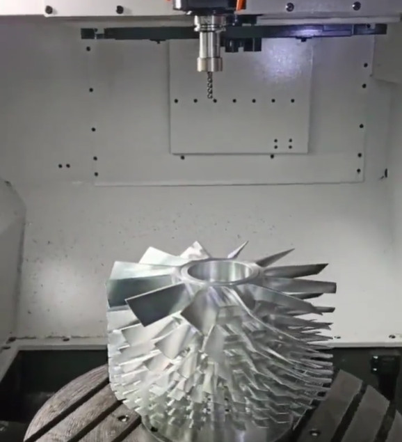
The impeller in a turbomolecular pump consists of multiple stages of rotor and stator blades, with the rotor rotating at high speeds to impart momentum to gas molecules. The impeller’s hub, shaft, and blade assembly must maintain strict concentricity to prevent imbalance, which could compromise the pump’s ability to achieve ultra-high vacuum levels (e.g., 10⁻³ to 10⁻¹¹ mbar). A CMM is ideal for this task due to its ability to capture precise 3D coordinates and calculate the median axis of the impeller relative to a datum.
Role of Coordinate Measuring Machine in Concentricity Measurement
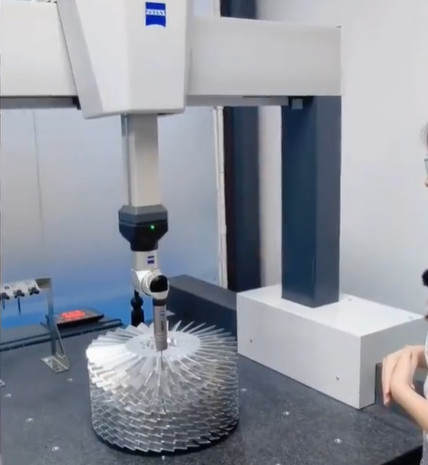
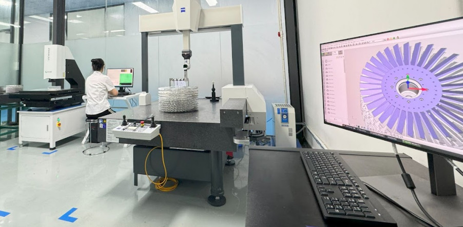
A CMM is a precision measurement device that uses a probe to collect 3D coordinate data from an object’s surface. It compares these measurements against a CAD model or predefined tolerances to assess geometric characteristics like concentricity. For turbomolecular pump impellers, the CMM’s high accuracy (typically within 0.002 mm) makes it suitable for measuring complex geometries and ensuring compliance with tight tolerances.
Key advantages of using a CMM include:
- High Precision: Capable of measuring features with tolerances as low as 0.002 mm, critical for high-precision components like impellers.
- Multi-Feature Measurement: Allows simultaneous measurement of multiple geometric features in a single setup, reducing time and setup errors.
- Non-Destructive: The CMM probe makes light contact, minimizing the risk of damaging delicate impeller surfaces.
- Data Reporting: Generates detailed reports for quality control and process validation.
The CMM operates by moving a probe along three axes (X, Y, Z) to collect data points. These points are used to construct geometric features, such as circles or cylinders, and calculate their central axes. For concentricity, the CMM determines the median points of the impeller’s cylindrical features and verifies their alignment within the specified tolerance zone.
Step-by-Step Procedure for Verifying Concentricity
The process of verifying the concentricity of a turbomolecular pump impeller using a CMM involves several steps, each requiring careful setup and execution to ensure accurate results. Below is a detailed procedure tailored to the impeller’s geometry and operational requirements.
Step 1: Preparation and Setup
Before measurement, ensure the CMM is calibrated and the environment is controlled (e.g., temperature at 20°C ± 1°C, humidity 40–60%) to minimize thermal expansion or contraction effects. The impeller should be cleaned to remove contaminants that could affect probe accuracy.
- Fixture Design: Secure the impeller in a custom fixture that aligns the datum axis (typically the shaft or bore) with the CMM’s coordinate system. The fixture should minimize movement without applying excessive clamping force, which could deform the impeller.
- Datum Selection: Identify the datum feature, usually the impeller’s shaft or central bore, as the reference axis. For example, a cylindrical bore with a diameter of 20 mm ± 0.01 mm may serve as Datum A.
- Probe Selection: Use a spherical or needle-shaped stylus with a diameter of 1–2 mm for precise contact with the impeller’s surfaces. Ensure the probe is calibrated for the expected measurement range.
Step 2: Establishing the Datum Axis
The datum axis is the reference against which concentricity is measured. To establish it:
- Position the CMM probe to touch multiple points (at least 8–12) around the circumference of the datum feature (e.g., the bore or shaft) at several cross-sections along its length.
- Use the CMM software to fit a cylinder to these points, calculating the central axis. For a bore with a length of 50 mm, measure at least three cross-sections (e.g., at 10 mm, 25 mm, and 40 mm from one end).
- Verify that the fitted cylinder’s axis aligns with the CAD model’s theoretical axis, ensuring the datum is accurately defined.
The accuracy of the datum axis is critical, as errors here will propagate to subsequent measurements. A tolerance of ±0.005 mm for the datum axis is typical for turbomolecular pump components.
Step 3: Measuring the Target Feature
The target feature is the cylindrical surface of the impeller (e.g., the outer diameter of the hub or blade root) whose concentricity is to be verified. Follow these steps:
- Collect data points on the target feature’s surface, typically at multiple cross-sections. For an impeller hub with a diameter of 100 mm ± 0.02 mm, measure at least 12 points per cross-section at three axial locations (e.g., 15 mm, 30 mm, and 45 mm from the reference plane).
- Use the CMM software to fit a cylinder to these points and calculate the median axis of the target feature.
- Ensure the probe contacts the surface lightly to avoid scratches, especially on polished or delicate impeller surfaces.
Step 4: Calculating Concentricity
Concentricity is determined by comparing the median points of the target feature’s cylinder to the datum axis. The CMM software performs the following:
- Constructs midpoints from diametrically opposite points on the target feature’s cross-sections.
- Verifies that these midpoints lie within a cylindrical tolerance zone centered on the datum axis. For example, a concentricity tolerance of ◎Φ0.01 mm means all median points must fall within a 0.01 mm diameter cylinder around the datum axis.
- Reports the maximum deviation of any midpoint from the datum axis as the concentricity value.
A typical concentricity tolerance for a turbomolecular pump impeller is 0.005–0.01 mm, reflecting the need for high precision in vacuum applications.
Step 5: Validation and Reporting
After measurement, validate the results by repeating the process with a different probe or setup to ensure repeatability. Generate a detailed report including:
- Coordinates of all measured points.
- Fitted cylinder parameters (diameter, axis orientation).
- Concentricity value and pass/fail status against the specified tolerance.
- Graphical representation of the tolerance zone and median points.
Store the data for traceability and quality assurance, especially in industries like aerospace or semiconductor manufacturing where turbomolecular pumps are critical.
Key Parameters for Concentricity Measurement
The following table summarizes critical parameters for measuring the concentricity of a turbomolecular pump impeller using a CMM:
| Parameter | Description | Typical Value |
|---|---|---|
| Datum Feature | Cylindrical bore or shaft serving as the reference axis | Diameter: 20 mm ± 0.01 mm |
| Target Feature | Impeller hub or blade root cylinder | Diameter: 100 mm ± 0.02 mm |
| Concentricity Tolerance | Maximum allowable deviation of median points | ◎Φ0.01 mm |
| Number of Points | Data points per cross-section for accurate cylinder fitting | 12–16 points |
| Cross-Sections | Number of axial locations measured | 3–5 sections |
| Probe Type | Spherical or needle-shaped stylus | 1–2 mm diameter |
Practical Considerations for Accurate Measurement
While CMMs offer high precision, several factors can affect measurement accuracy. Addressing these ensures reliable results:
- Environmental Control: Maintain stable temperature and humidity to prevent thermal distortion. A variation of 1°C can cause a 0.011 mm expansion in a 100 mm steel impeller.
- Fixture Stability: Use a rigid fixture to prevent movement during measurement. Vibration from nearby equipment can introduce errors of 0.001–0.003 mm.
- Probe Calibration: Regularly calibrate the probe to ensure accuracy within 0.001 mm.
- Surface Quality: Ensure the impeller’s surfaces are free of burrs or contaminants, as these can cause probe deflections of up to 0.005 mm.
- Software Settings: Configure the CMM software to use high-density point sampling and robust curve-fitting algorithms for accurate cylinder construction.
Additionally, operators should be trained in CMM operation and GD&T principles to interpret results correctly and avoid setup errors.
Alternative Methods and Their Limitations
While CMM is the preferred method for concentricity verification, alternative methods like dial gauges or optical comparators are sometimes used. However, these have limitations:
- Dial Gauge: Measures runout rather than true concentricity, as it relies on surface contact rather than median points. It risks scratching delicate surfaces and is operator-dependent, with potential errors of 0.01–0.05 mm.
- Optical Comparator: Suitable for 2D measurements but struggles with complex 3D geometries like impellers. Accuracy is limited to 0.01 mm, insufficient for ultra-high vacuum applications.
CMMs overcome these limitations by providing 3D measurement capability, non-destructive probing, and automated data analysis, making them the industry standard for turbomolecular pump impellers.
Conclusion
Verifying the concentricity of a turbomolecular pump impeller using a CMM is a systematic process that ensures the component meets stringent GD&T requirements. By carefully setting up the datum axis, measuring the target feature, and analyzing median points within a cylindrical tolerance zone, manufacturers can confirm the impeller’s alignment with tolerances as tight as 0.005–0.01 mm. The use of a CMM, combined with proper environmental control, fixture design, and operator training, ensures high precision and reliability. This process is critical for maintaining the performance and longevity of turbomolecular pumps in demanding applications like semiconductor manufacturing and vacuum technology.