Turbine impellers are critical components in turbomachinery, widely used in aerospace, automotive, and energy industries due to their complex geometries and high-performance requirements. The intricate, twisted blade structures and free-form surfaces of impellers demand advanced manufacturing techniques. DMG five-axis machining centers, known for their precision and flexibility, are ideal for producing such components. This study explores the optimization of five-axis machining paths for turbine impellers, focusing on tool path generation, parameter settings, and simulation techniques to achieve high accuracy and efficiency. The content is grounded in technical expertise, emphasizing systematic approaches and practical implementation.
Understanding Turbine Impeller Geometry
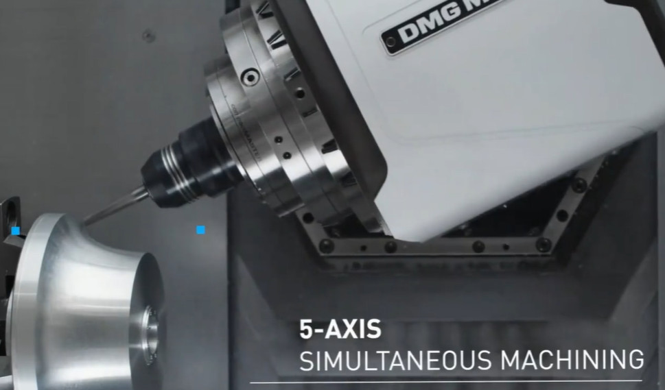
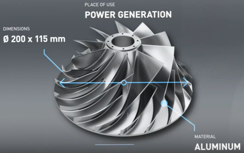
Turbine impellers, particularly centrifugal impellers, feature complex three-dimensional geometries, including twisted blades, hubs, and leading/trailing edges. These components are typically made from materials like titanium alloys or NiAl-based superalloys, which are difficult to machine due to their high strength and thermal resistance. The blades often have thin-walled, free-form surfaces with significant curvature, requiring precise control to avoid deflection errors or surface inaccuracies. Five-axis machining is preferred over three-axis methods because it allows simultaneous control of tool orientation and position, enabling access to challenging areas without multiple setups.
The geometry of an impeller includes several key elements:
- Hub: The central structure connecting the blades, often requiring precise milling to maintain dimensional accuracy.
- Blades: Twisted, thin-walled structures with complex curvature, critical for aerodynamic performance.
- Leading and Trailing Edges: Aerodynamically critical areas that demand high surface quality to minimize flow losses.
- Passage Width: The space between blades, which can be narrow, necessitating slender tools and careful path planning.
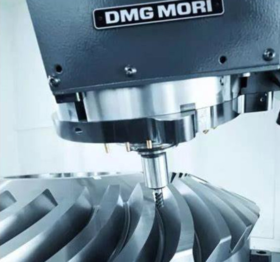
These geometric features require a machining strategy that balances precision, tool life, and production efficiency. DMG five-axis machines, such as the DMC210FD, provide the necessary flexibility with their multi-axis control and robust spindle designs.
Tool Path Generation for Five-Axis Machining
Effective tool path generation is the cornerstone of impeller machining. The goal is to create collision-free, smooth tool paths that minimize machining time while ensuring surface quality. DMG five-axis machining centers utilize advanced CAM software, such as Siemens NX or Mastercam, to generate optimized tool paths. The process involves several steps:
- Geometry Analysis: The impeller’s CAD model is analyzed to identify critical features, such as blade curvature and passage width. This step ensures that the tool path respects geometric constraints.
- Tool Selection: Ball-end or conical cutters are commonly used for impeller machining. For example, a D8R1 ball-end mill is often selected for roughing and finishing blade surfaces due to its versatility.
- Path Planning: The tool path is divided into roughing, semi-finishing, and finishing stages. Roughing removes excess material, semi-finishing refines the surface, and finishing achieves the final geometry.
- Simulation: Tools like Vericut are used to simulate the machining process, checking for collisions, overcutting, or undercutting.
A notable approach is flank milling, where the side of the cutter is used to machine ruled surfaces, reducing machining time compared to point milling. Studies have shown that flank milling with a conical cutter can achieve machining accuracy errors as low as 0.007–0.012 mm. The tool path is often generated using Non-Uniform Rational B-Spline (NURBS) curves to ensure smooth transitions and minimize vibrations.
| Stage | Tool Type | Cutting Speed (m/min) | Feed Rate (mm/tooth) | Step Interval (mm) |
|---|---|---|---|---|
| Roughing | D8R1 Ball-End Mill | 100–150 | 0.1–0.2 | 0.5–1.0 |
| Semi-Finishing | Conical Cutter | 120–180 | 0.05–0.1 | 0.2–0.5 |
| Finishing | Ball-End Mill | 150–200 | 0.02–0.05 | 0.05–0.1 |
The table above outlines typical parameters used in DMG five-axis machining for impeller production. These parameters are adjusted based on material properties and machine capabilities to optimize performance.
Optimization Techniques for Machining Paths
Path optimization focuses on reducing machining time, minimizing tool wear, and ensuring surface accuracy. Several techniques are employed:
- Cutter-Workpiece Engagement (CWE) Modeling: Accurate calculation of the CWE region improves cutting force predictions, enhancing path precision. NURBS-based CWE modeling has been shown to optimize cutting parameters for turbine blades.
- Genetic Algorithms (GA): GA is used to optimize workpiece setup and tool orientation, reducing angular accelerations of rotary axes. This approach minimizes dynamic loading, improving machine stability.
- Simulated Annealing-Particle Swarm Optimization (SA-PSO): This fusion algorithm iteratively optimizes tool paths for side milling, achieving convergence in approximately 6–7 iterations with reduced surface errors.
- B-Spline Curves: B-spline curves are used to smooth tool paths, minimizing jerk (rate of change of acceleration) and reducing vibrations. This enhances surface quality and tool life.
For example, a study optimizing impeller machining with SA-PSO reduced machining errors to 0.007 mm by adjusting tool axis trajectories. Another approach, response surface methodology (RSM), optimizes rough cutting parameters, achieving up to 25% reduction in cutting forces and 60% reduction in average cutting force instability.
DMG machines, such as the JDGR200 V, incorporate direct-drive spindles (e.g., 44 kW, 1550 Nm) to minimize thermal growth and maintain accuracy during high-speed machining. These machines also support real-time feedback through on-machine measurement systems, allowing dynamic path adjustments.
Deflection Error Minimization
Thin-walled impeller blades are prone to deflection errors due to cutting forces and temperatures. These errors can result in overcutting or undercutting, compromising dimensional accuracy. To address this, virtual machining systems using finite element analysis (FEA) predict and minimize deflection errors. The process involves:
- Force Modeling: Cutting forces are calculated based on tool geometry and material properties. For instance, milling a NiAl-based superalloy impeller requires precise force control to avoid blade deformation.
- FEA Simulation: FEA models the blade’s response to cutting forces, identifying areas of high deflection risk.
- Parameter Optimization: Genetic algorithms or RSM adjust feed rates and spindle speeds to minimize deflection. For example, a feed rate of 0.02 mm/tooth and spindle speed of 2000 rpm can reduce deflection errors to below 0.01 mm.
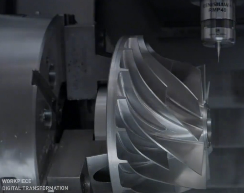
- Validation: Post-machining inspection using coordinate measuring machines (CMM) verifies accuracy, with studies reporting deviations as low as 0.005 mm.
DMG’s integrated stiffness models, based on multi-body dynamics and force ellipsoid methods, further enhance accuracy by optimizing tool posture and machine rigidity. These models ensure that the machining system maintains stability across various tool orientations.
Simulation and Verification
Simulation is critical for validating tool paths before machining. Vericut and Siemens NX provide robust platforms for virtual machining, allowing engineers to:
- Detect collisions between the tool and workpiece.
- Identify overcutting or undercutting risks.
- Optimize tool paths to reduce machining time.
For instance, Vericut simulations for a titanium alloy impeller confirmed collision-free paths with a machining accuracy of 0.01 mm. The simulation process involves setting tool libraries, defining CNC programs, and adjusting parameters like step intervals (e.g., <28 μm for finishing). These simulations reduce trial-and-error on physical machines, saving time and costs.
Post-machining, CMM inspection ensures that the impeller meets tolerances. A typical tolerance for impeller blades is 10 microns, achievable with optimized five-axis paths on DMG machines.
Practical Implementation on DMG Machines
DMG five-axis machining centers, such as the DMC210FD and DMF180, are equipped with features that enhance impeller machining:
| Feature | Description | Benefit |
|---|---|---|
| Direct-Drive Spindle | 44 kW, 1550 Nm, minimal thermal growth | Maintains accuracy during high-speed operations |
| 210° B-Axis Head | Flexible spindle orientation | Accesses complex geometries without repositioning |
| Epoxy-Polymer Bed | Vibration-damping material | Reduces chatter, improves surface finish |
These features, combined with advanced CAM software, enable efficient machining of impellers. For example, the DMC210FD’s 5-pallet carousel allows off-line fixturing, reducing setup times by up to 17% compared to three-axis machines.
Conclusion
Optimizing DMG five-axis machining paths for turbine impellers requires a systematic approach, integrating geometry analysis, tool path generation, optimization algorithms, deflection error control, and simulation. By leveraging advanced CAM tools, precise parameter settings, and robust machine features, manufacturers can achieve high accuracy (e.g., 0.007–0.012 mm) and efficiency. The techniques discussed, such as NURBS-based path planning, SA-PSO optimization, and FEA-based deflection control, provide a reliable framework for producing high-quality impellers. This study underscores the technical prowess of DMG five-axis machining centers in addressing the complex demands of impeller manufacturing.