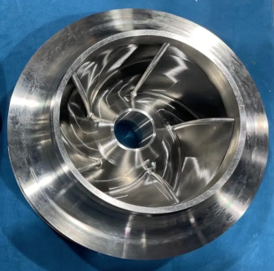
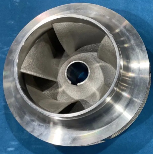
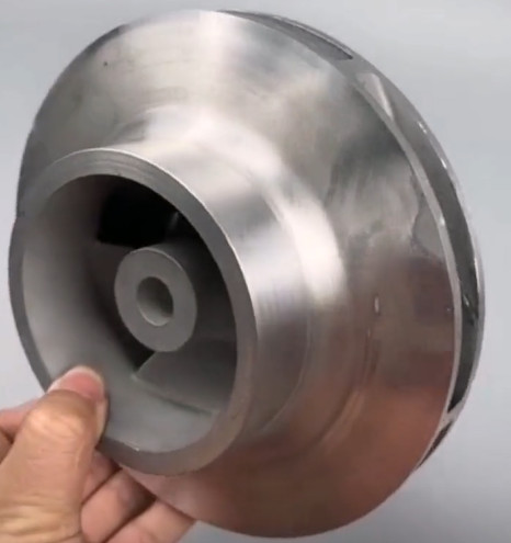
The 3D printing process, or additive manufacturing (AM), has transformed the production of complex components like centrifugal impellers. These rotating components are critical in turbomachinery, such as centrifugal pumps and compressors, where precision, durability, and performance are paramount. To ensure high-quality outcomes, manufacturers must focus on four key control points: material selection, design optimization, printing parameter control, and post-processing. This guide provides a detailed, technical overview of these control points, emphasizing systematic approaches and precise parameters to achieve reliable results.
Material Selection
Material selection is the foundation of the 3D printing process for centrifugal impellers. The chosen material must withstand high rotational speeds, resist corrosion, and maintain structural integrity under operational stresses. Common materials include metals like Inconel 718, 316L stainless steel, and titanium alloys (e.g., TiAl6V4), as well as polymers like carbon fiber-reinforced polyamide for less demanding applications.
Key considerations include mechanical properties, such as tensile strength and fatigue resistance, and compatibility with the 3D printing technology, such as laser powder bed fusion (LPBF) or fused deposition modeling (FDM). For example, Inconel 718, used in high-performance impellers, offers a tensile strength of approximately 1,240 MPa and is suitable for LPBF due to its fine powder form. The material's thermal conductivity and melting point also influence printing parameters, requiring precise laser power and scanning strategies.
Material density is another critical factor. For instance, a 3D-printed Inconel 718 impeller can achieve 99.9% density, minimizing porosity that could lead to stress concentrations. Manufacturers must verify material certifications and conduct tests, such as X-ray computed tomography, to ensure powder quality and absence of defects. For polymeric impellers, carbon fiber-reinforced polyamide with a tensile strength of 100–150 MPa is often selected for prototyping or low-pressure applications, but its anisotropy requires careful orientation during printing.

Design Optimization
Design optimization ensures that the impeller geometry meets functional requirements while leveraging the capabilities of 3D printing. Unlike traditional manufacturing, AM allows for complex geometries, such as lattice structures or internal channels, but requires precise control to avoid defects. The design process involves computer-aided design (CAD) modeling, computational fluid dynamics (CFD) analysis, and finite element analysis (FEA).
Key geometric parameters include impeller diameter, blade angle, number of blades, and blade curvature. For example, an impeller with a diameter of 200 mm and blade outlet angles of 30–35° can achieve optimal hydraulic efficiency, with a head of 35–40 m and efficiency of 80–85%. CFD simulations help optimize blade profiles to minimize turbulence and cavitation, while FEA ensures structural integrity under rotational speeds up to 60,400 rpm, where stresses may reach 255 MPa.
Reverse engineering is often used to create CAD models from existing impellers. Software like UG CAD/CAM facilitates surface modeling, dividing the impeller into hub and blade surfaces. The blade surface comprises camber, suction, and pressure surfaces, each requiring precise control to ensure aerodynamic performance. For LPBF, support structures must be designed to minimize deformation, especially for low-angle features (e.g., 2–3.8° cover angles). A common issue is the formation of melt pool instabilities, which can create small defects on overhangs, requiring optimized support strategies.
| Parameter | Typical Value | Purpose |
|---|---|---|
| Impeller Diameter | 150–300 mm | Controls head and flow rate |
| Blade Outlet Angle | 30–35° | Optimizes hydraulic efficiency |
| Number of Blades | 5–8 | Balances efficiency and complexity |
Printing Parameter Control
Printing parameter control is critical to achieving dimensional accuracy, surface quality, and mechanical properties in 3D-printed impellers. Parameters such as laser power, scanning speed, layer thickness, and hatch spacing directly influence the build quality. For LPBF, typical settings for Inconel 718 include a laser power of 200–400 W, scanning speed of 800–1,200 mm/s, layer thickness of 20–50 μm, and hatch spacing of 80–120 μm. These parameters ensure a melt pool depth of 50–100 μm, achieving high density and minimal porosity.
Layer thickness affects build time and surface roughness. A thinner layer (e.g., 20 μm) improves resolution but increases printing time, while a thicker layer (e.g., 50 μm) reduces time but may compromise accuracy. Scanning strategies, such as zigzag or stripe patterns, influence residual stress. For example, a stripe pattern with a 67° rotation per layer reduces stress concentrations, improving structural integrity.
Thermal management is another critical aspect. Preheating the build plate to 100–200°C minimizes thermal gradients, reducing residual stresses that could cause deformation. In a study of a TiAl6V4 lattice impeller printed on an SLM280 printer, adjusting laser power by 10% reduced residual stress by 15–20%. Manufacturers must also monitor powder bed conditions to prevent issues like re-coater jamming, which can disrupt layer bonding. Simulation tools like ANSYS Workbench can predict thermal history and deformation, allowing parameter adjustments before printing.
| Parameter | Typical Range | Impact |
|---|---|---|
| Laser Power | 200–400 W | Affects melt pool depth and density |
| Scanning Speed | 800–1,200 mm/s | Influences build time and surface quality |
| Layer Thickness | 20–50 μm | Controls resolution and build time |

Post-Processing
Post-processing is essential to achieve the final performance and quality of 3D-printed impellers. This stage includes support removal, heat treatment, surface finishing, and dimensional inspection. Each step addresses specific issues arising from the AM process, such as residual stresses, surface roughness, and geometric deviations.
Support removal is the first step, often performed manually or with wire electrical discharge machining (EDM) for metal impellers. For Inconel 718 impellers, supports are removed from areas with low overhang angles (e.g., 2.5–3.8°), ensuring minimal damage to the surface. Heat treatment, such as stress-relief annealing at 980°C for 1 hour, reduces residual stresses by 30–40%, improving fatigue life. Hot isostatic pressing (HIP) at 1,200°C and 100 MPa can further increase density to 99.99%, eliminating internal voids.
Surface finishing enhances hydraulic efficiency by reducing roughness. Abrasive flow machining (AFM) is effective for closed impellers, using a viscous medium with abrasive grits to polish internal vanes. AFM can reduce surface roughness from Ra 6–8 μm to Ra 0.5–1 μm, improving pump efficiency by 2–3%. For polymeric impellers, chemical post-treatment with dimethyl ketone smooths surfaces, enhancing performance compared to untreated FDM parts.
Dimensional inspection ensures compliance with tolerances, typically ±0.05 mm for critical features like blade thickness (1–1.5 mm). Techniques like coordinate measuring machines (CMM) and laser scanning verify geometry. Non-destructive testing, such as dye penetrant inspection, detects surface cracks, while ultrasonic testing identifies internal defects. A 500-hour bench test under real-life conditions (e.g., 25,000 rpm) validates performance, monitoring parameters like head, flow rate, and efficiency.
Conclusion
The 3D printing process for centrifugal impellers requires meticulous control over four key points: material selection, design optimization, printing parameter control, and post-processing. By selecting appropriate materials like Inconel 718 or carbon fiber-reinforced polymers, optimizing designs with CFD and FEA, controlling printing parameters like laser power and layer thickness, and applying rigorous post-processing techniques, manufacturers can produce high-performance impellers. These steps, supported by precise parameters and systematic approaches, ensure reliability, efficiency, and durability in demanding applications like centrifugal pumps and compressors.
