Impeller machining requires exceptional precision due to its critical role in applications like aerospace, automotive, and energy systems. Achieving a concentricity error of 0.002mm is a stringent requirement that demands meticulous control over every aspect of the machining process. This guide provides a systematic approach to achieving this tolerance, focusing on material selection, tooling, machining strategies, fixturing, and inspection methods. The content is based on established practices and technical expertise to ensure reliability and repeatability.
Understanding Concentricity in Impeller Machining
Concentricity, as defined by ASME Y14.5, is a geometric dimensioning and tolerancing (GD&T) characteristic that measures how closely the median points of a cylindrical feature align with a datum axis. In impeller machining, concentricity ensures that the central shaft hole, blades, and hub share a common axis, minimizing vibration, wear, and performance degradation during high-speed rotation. A tolerance of 0.002mm is exceptionally tight, typically reserved for high-performance impellers in aerospace engines or precision pumps.
Concentricity differs from runout, which measures surface deviations, and coaxiality, which focuses on axis alignment. To achieve 0.002mm concentricity, the machining process must control both the form and position of features, accounting for material properties, tool deflection, and machine accuracy. The following sections detail the critical factors and methods involved.
Material Selection and Preparation
The choice of material significantly impacts concentricity control. Impellers are often made from forged aluminum alloys (e.g., ASTM B247), titanium alloys, or stainless steel due to their strength and durability. Material properties such as homogeneity, residual stress, and thermal expansion affect machining precision.
- Material Quality: Use high-quality, pre-turned, ground, and polished bar stock to ensure initial roundness. Oval or irregular stock can introduce concentricity errors, requiring additional machining passes.
- Heat Treatment: Perform stress-relieving heat treatment before machining to minimize distortion. For example, aluminum alloys should be solution-treated and aged to stabilize microstructure.
- Blank Preparation: Pre-machine blanks to near-final dimensions to reduce material removal during final machining, which helps maintain dimensional stability.
For a 430mm diameter impeller, the raw material blank should have a roundness error of less than 0.01mm and a surface finish of Ra 1.6μm to provide a stable starting point for precision machining.
Tooling and Machine Selection
High-precision tooling and machines are essential for achieving 0.002mm concentricity. The following parameters and equipment are recommended based on industry practices.
| Parameter | Specification | Purpose |
|---|---|---|
| Machine Type | 5-axis CNC machining center (e.g., GROB 350) | Enables simultaneous control of multiple axes for complex impeller geometry |
| Spindle Speed | 24,000 rpm | Minimizes vibration and ensures fine surface finish |
| Positioning Accuracy | 0.001mm | Ensures precise tool path control |
| Tool Material | Carbide or PCD (Polycrystalline Diamond) | Reduces tool wear and deflection |
| Tool Runout | < 0.002mm | Prevents eccentricity during cutting |
Tool holders should use hydraulic or shrink-fit systems to minimize runout. Regular calibration of the machine tool, including spindle alignment and axis compensation, is critical to maintain accuracy. For instance, a spindle misalignment of 0.001mm can directly contribute to concentricity errors.
Machining Strategies
The machining process must be carefully planned to minimize errors. The following strategies are effective for impeller machining:
- Single Setup Machining: Perform all critical features (e.g., central shaft hole, hub, and blade roots) in a single setup to eliminate rechucking errors. For example, machine the central shaft hole and hub in one operation using a 5-axis CNC center.
- Layered Cutting: Use a layered cutting approach to reduce blade deformation. For a 300mm blade height, divide the machining into 10 layers, each removing 0.5mm of material, with a feed rate of 0.1mm/rev and cutting speed of 200m/min.
- Finite Element Analysis (FEA): Optimize machining parameters using FEA to predict and compensate for blade deflection. For instance, adjust tool paths to account for a 0.001mm deflection under cutting forces.
- Adaptive Machining: Use in-process measurement systems to monitor tool wear and adjust parameters in real-time. This ensures consistent material removal and prevents overcutting.
For the central shaft hole, use a boring tool with a diameter of 50mm and a tolerance of H6 (0/+0.012mm) to achieve a concentricity baseline. Finish machining should employ a polishing pass to achieve a surface roughness of Ra 0.8μm, reducing friction and wear during inspection.
Fixturing and Workholding
Proper fixturing is critical to maintaining concentricity during machining. Improper clamping can introduce distortion or misalignment, compromising tolerance.
- Custom Fixtures: Design fixtures to hold the impeller rigidly, minimizing vibration. For a 430mm impeller, use a three-point clamping system with a clamping force of 5000N to ensure stability.
- Datum Alignment: Align the fixture with the machine’s datum axis using a dial indicator with a resolution of 0.0005mm. The datum axis should coincide with the impeller’s central shaft hole.
- Soft Jaws: Use soft jaws machined in-situ to match the impeller’s geometry, reducing runout. For example, bore soft jaws to a diameter of 100mm with a runout of less than 0.001mm.
- Tailstock Support: For long impellers, use a tailstock to support the free end, reducing deflection. The tailstock should apply a force of 1000N and be aligned within 0.001mm of the spindle axis.
Regular inspection of fixtures for wear or deformation is necessary. A worn fixture can introduce errors exceeding 0.002mm, negating other control measures.
Inspection and Measurement
Accurate measurement is essential to verify concentricity. The complexity of concentricity measurement requires advanced equipment and rigorous procedures.
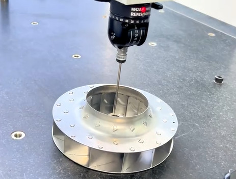
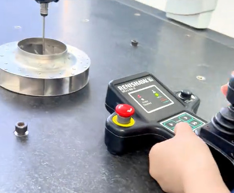
- Coordinate Measuring Machine (CMM): Use a CMM with a probing accuracy of 0.0005mm to measure the median points of the central shaft hole and hub. Take 8 points per cross-section at 10 axial locations to construct the median axis.
- Laser Micrometer: Employ a laser micrometer for non-contact measurement of blade concentricity, ensuring no deformation during inspection. The micrometer should have a resolution of 0.0001mm.
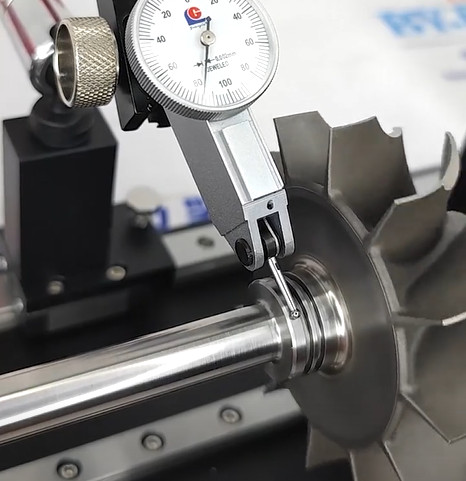
- Dial Indicator: For shop-floor checks, use a dial indicator with a resolution of 0.0005mm to measure runout as a proxy for concentricity. However, runout includes circularity errors, so CMM verification is preferred.
- Measurement Protocol: Rotate the impeller 360° during measurement to capture all median points. Ensure the part is fixtured identically to the machining setup to avoid positional errors.
The tolerance zone for 0.002mm concentricity is a cylindrical zone with a diameter of 0.002mm. All median points must fall within this zone. If measurements indicate a deviation of 0.003mm, adjust the tool offset by 0.001mm and re-machine the feature.
Process Control and Documentation
Maintaining 0.002mm concentricity requires robust process control and documentation to ensure repeatability.
- Statistical Process Control (SPC): Monitor key parameters (e.g., tool wear, spindle runout) using SPC charts. Maintain a CpK value of at least 1.33 for critical dimensions.
- Tool Life Management: Replace tools after 50 machining cycles or when wear exceeds 0.01mm to prevent dimensional drift.
- Operator Training: Train operators on GD&T principles and CMM operation to ensure consistent measurement practices.
- Documentation: Record all machining parameters, inspection results, and fixture alignments in a digital log. For example, document spindle speed, feed rate, and tool runout for each impeller batch.
Adherence to AS9102 standards for aerospace impellers ensures traceability and compliance with customer requirements.
Common Issues and Solutions
Despite careful planning, issues may arise during impeller machining. The following table addresses common problems and their solutions.
| Issue | Cause | Solution |
|---|---|---|
| Concentricity exceeds 0.002mm | Spindle misalignment | Recalibrate spindle to within 0.0005mm using a test bar |
| Blade deformation | Excessive cutting force | Reduce feed rate to 0.08mm/rev and use FEA to optimize tool path |
| Fixture runout | Worn soft jaws | Re-bore soft jaws in-situ to achieve runout < 0.001mm |
Proactive monitoring and calibration can prevent these issues from impacting production.
Conclusion
Achieving a concentricity error of 0.002mm in impeller machining is a complex but achievable goal with the right approach. By selecting high-quality materials, using precision tooling and machines, implementing optimized machining strategies, employing robust fixturing, and verifying results with advanced inspection methods, manufacturers can meet this stringent tolerance. Process control and documentation ensure repeatability, while addressing common issues enhances reliability. This systematic approach delivers high-performance impellers that meet the demands of critical applications.